ABU 6500C3 CT Mag Strip
Although this article is on the C3 CT 07, it equally applies to other ABU 6500’s (although part numbers will vary). I am not an expert reel technician and this is not meant to be an egg sucking exercise for those who are already familiar with stripping down a reel. This has been done as a guide on to how I strip and clean a reel in the hope that it may help those who are not used to taking these apart. The one being used here is the twin of the one I stupidly left behind after a recent session and was until now used as a ‘donor’ reel for parts.
Hyperlinked part names link to their respective part numbers in the Parts List at the end of the end of the page. Parts and their part numbers shown here pertain to this particular model, so may differ from other reels depending on model and year.
 Print This Post Beware, image heavy!
A list of things I use:
- Clean lint free cloths
- Suitable solvent (lighter fluid is good)
- Small flat blade screwdriver
- Small Phillips screwdriver
- Spanner to fit handle nut
- Reel oil
- Reel grease
- Small paintbrush
- Toothbrush
I find that having everything organised first saves time and makes it easier to find the bits that drop off (they will). I sometimes use an old white hand towel for laying the various parts on but for these photos, I didn’t have it, so used my favourite fishing sweatshirt.
The first thing to do is give the reel a good rinse and scrub with a toothbrush under running water to remove excess salt and crap and then dry. As you can see, I didn’t (again). Fig1
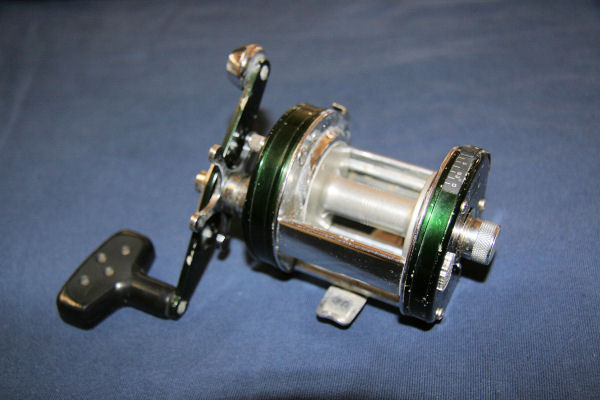
Fig 1: Before
Remove the small handle nut retaining tab screw and handle retaining tab around the handle nut . Undo the the handle nut and remove the handle. You may have to remove the small circlip on the top of the shaft to get the handle off but on mine, the handle will come off over it. Beware as this is a slippery little sucker and will fly off into a parallel universe. Next, remove the small handle spring washer and unwind the star drag adjuster until it comes off the shaft. Lay the items out in the order you remove them, to make it easier when re-assembling. Fig2.
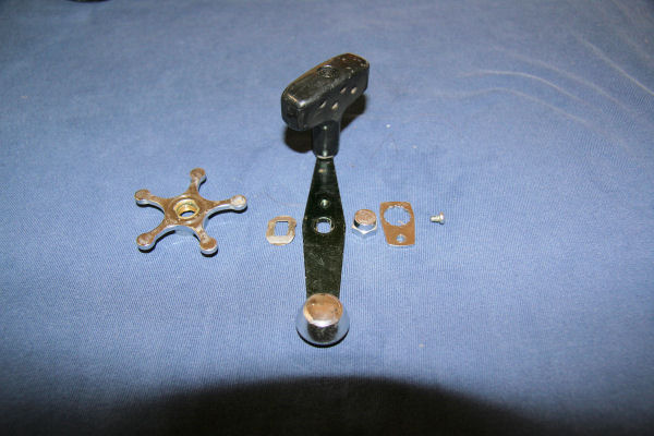
Fig 2: Handle and drag adjuster components.
Remove the two drag sprung washers from the drive shaft. Fig 3.
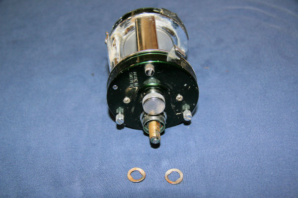
Fig 3: Sprung washers from drive shaft.
Undo the knurled tension cap on the end plate and remove the spindle retaining clip. Fig 4.
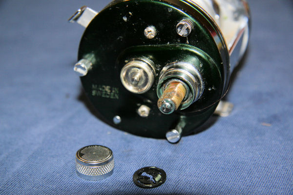
Fig 4: Spindle clip and right tension cap.
Undo the three knurled captive screws on the right hand side plate and remove it. Fig 5.
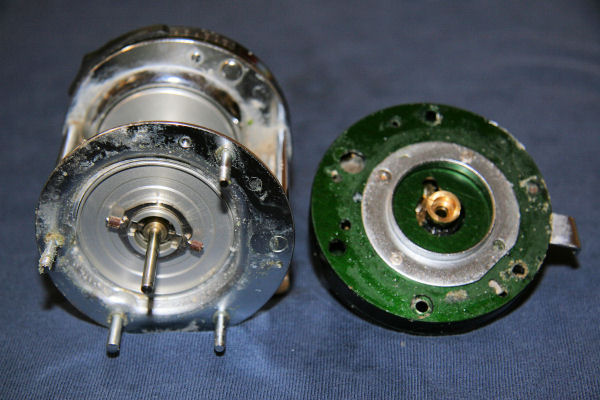
Fig 5: Right side plate removed revealing spool and spindle with brake blocks.
Remove the spool and spindle from the cage and put to one side. Fig 6. If you drop the brake blocks, finding them takes about the same amount of time and is about as successful as finding a cure for the common cold. Put them somewhere safe.
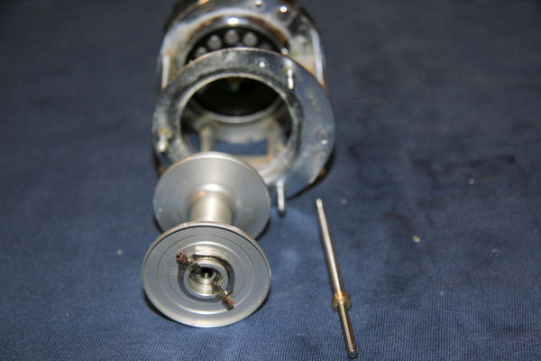
Fig 6: Spool and spindle removed from cage.
Undo the two smaller side plate screws to release the side plate from the brake plate and the internals. Fig 7.
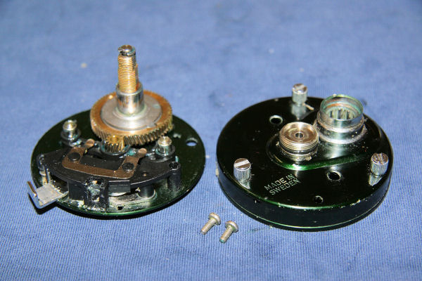
Fig 7: Side plate removed from brake plate, revealing clutch and drag system.
If not already done, remove the small circlip (heed the warning) at the top of the drive shaft and pull the shaft and drag assembly off the spindle. Fig 8.
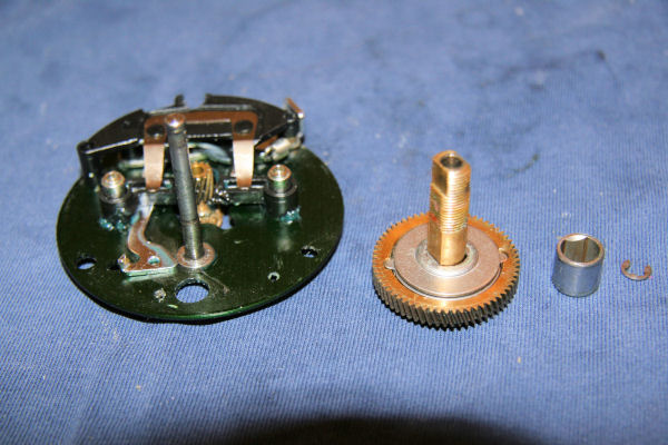
Fig 8: Drive shaft, main gear and drag assembly removed from spindle.
Now remove the main gear and drag system components from the gear shaft and lay them out in the order they came off. Look after them, as they are notoriously difficult and messy to retrieve from your pet. The drag components consist of a mixture of stainless steel washers and fibre washers Fig 9.
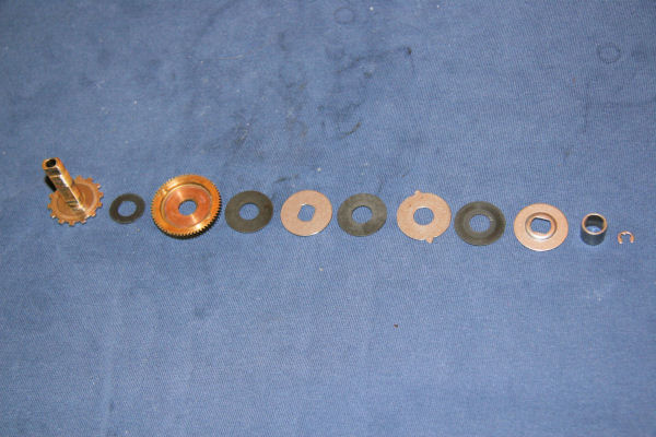
Fig 9: Drive shaft and drag system dismantled.
Remember to remove the small copper drive shaft shim from the base of the spindle and put it with the other drag washers. Fig 10.
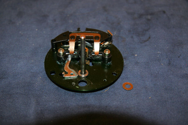
Fig 10: Drive shaft shim removed.
These components may well need a good clean to remove any oil or grease. The easiest way is to get a shallow container, put the components in and cover with lighter fluid (taking all necessary safety precautions of course) and agitate gently them gently for a short while before taking them out and laying on absorbent paper to dry thoroughly. Fig 11.
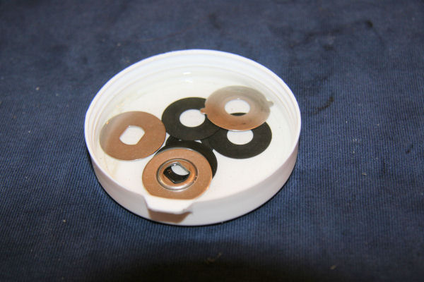
Fig 11: Cleaning components in lighter fluid.
Dismantle the clutch components and lay them out as they come off. Fig 12.
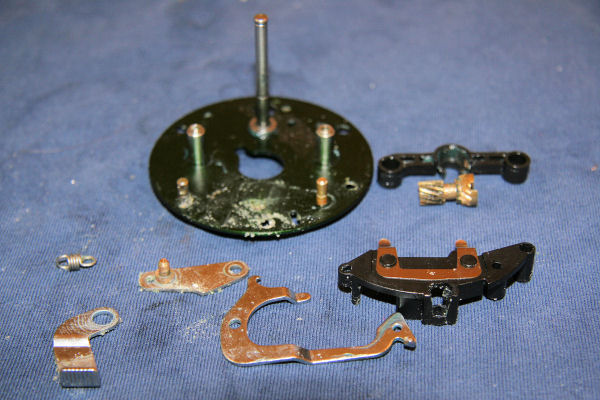
Fig 12: Clutch components
After a through clean and de-cack, dry and lightly grease before re-assembling in the following order: Place the connector arm back onto its post. Fig 13.

Fig 13: Connector arm on its post.
… Followed by the Clutch release push button. Fig 14.
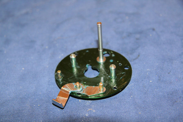
Fig 14: Clutch release push button.
..and the clutch release arm, not forgetting the small spring Fig 15.
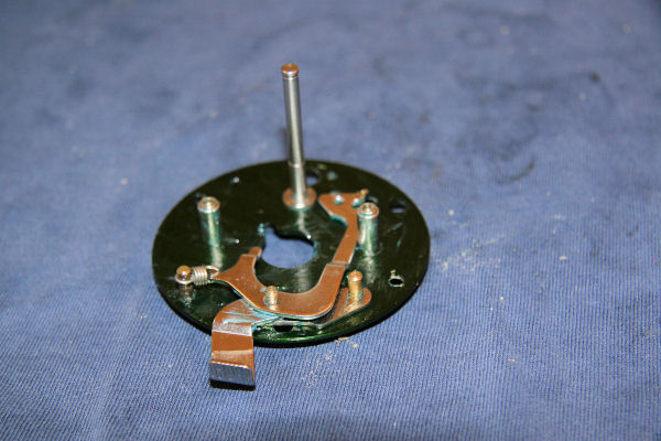
Fig 15: Clutch release arm and spring.
After cleaning and re-greasing, click the pinion gear back into the pinion gear yoke making sure it’s the right way in (wider section with the slot goes to the bottom) and push the yoke onto its posts. Fig 16.
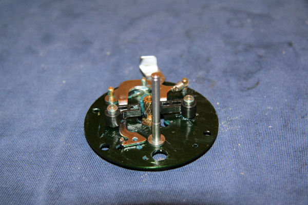
Fig 16: Pinion gear and yoke re-installed on posts.
Push the spool release pressure plate into position on its locating pins. Fig 17. This can be fiddly.
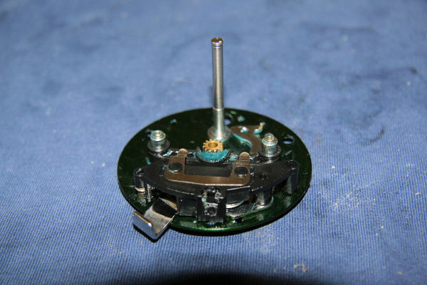
Fig 17: Spool release pressure plate in situ.
Now to re-assemble the drag system. Firstly, put the drive shaft shim back on the spindle. Fig 18.
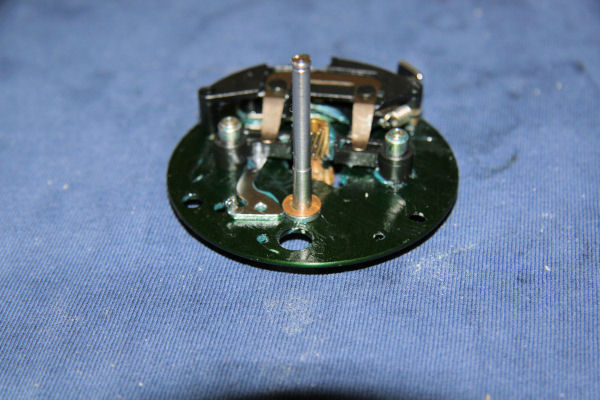
Fig 18: Drive shaft shim on spindle.
… Followed by the drive shaft itself. Fig 19.
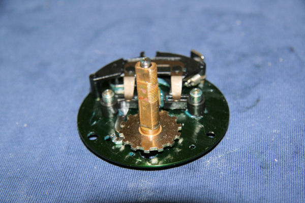
Fig 19: Drive shaft replaced on spindle.
Now put on the smaller of the fibre drag washers. Fig 20.Be careful not to get any grease on the washers. If you do, clean again in lighter fluid and dry thoroughly.
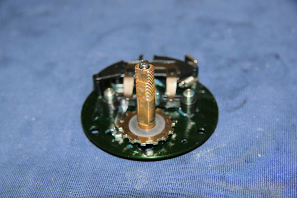
Fig 20: Small fibre washer installed.
Next, slide the main gear back onto the drive shaft. Fig 21.
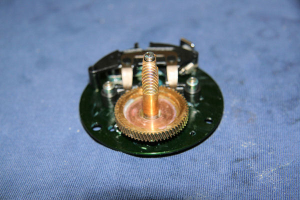
Fig 21: Main gear located on drive shaft.
…Followed by the drag washers, in this order: fibre, steel, fibre, tabbed steel, fibre, domed steel. Fig 22 and 23.
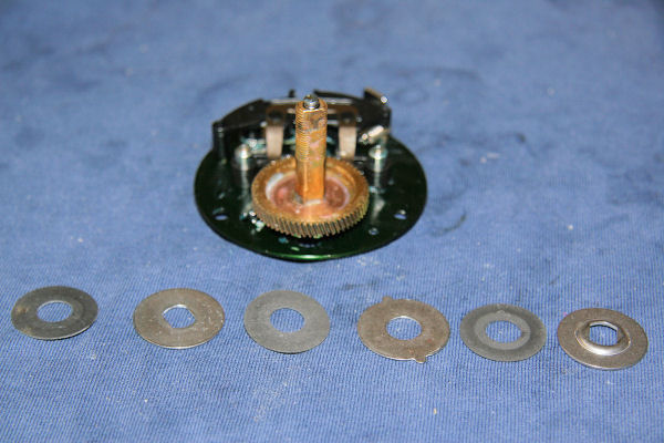
Fig 22: Drag washers in order L to R.
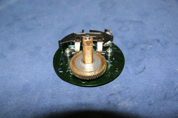
Fig 23: Drag washers in situ
After cleaning the side plate, add some grease to the IAR (Instant Anti Reverse) bearing located in the larger aperture. Fig 24.
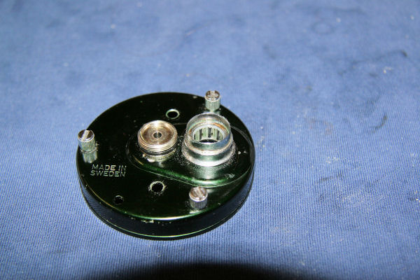
Fig 24: IAR bearing can be seen in the larger aperture.
Now lightly grease and the IAR bearing bush and slide over the drive shaft before replacing the side plate and securing with the two small screws. Fig 25. I should have photographed the bush but forgot; it’s the small stainless steel cylinder as seen in Fig 8 earlier.
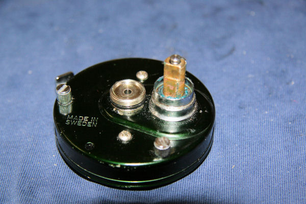
Fig 25: Sideplate replaced.
Pop the two sprung washers over the drive shaft and push them down onto the recess. Fig 26.
Now we go to the spool. It shouldn’t be necessary to remove the bearings, just a drop of oil to each should suffice. If they need to be removed, one is located under the circular brake block carrier on the right side. Fig 27.
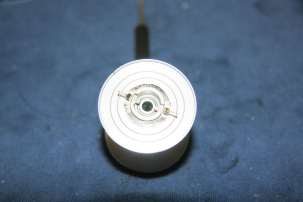
Fig 27: Right side spool bearing under brake block carrier.
… the other is under a thin wire retaining clip on the left side of the spool. Fig 28.
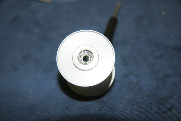
Fig 28: Left spool bearing under wire clip.
Lightly oil the spool spindle and insert it long section first into the right hand end of the spool until the brass collar fits snugly. Gently pop the brake blocks back onto the carrier pins being careful not to get oil or grease on them. Fig 29.
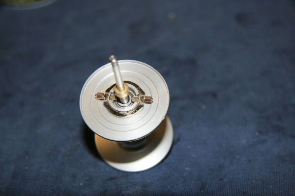
Fig 29: Spool and spool spindle.
Being careful not to dislodge the brake blocks, insert that end of the spindle into the right side plate. Fig 30.
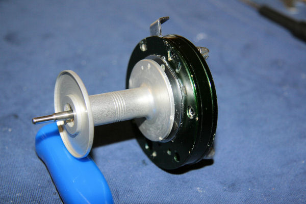
Fig 30: Spool and spindle re-installed into right side plate.
Clip the spindle retaining clip onto the end of the spindle and then screw back the tension cap. Fig 31.
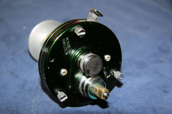
Fig 31: Tension cap replaced.
Now the drag adjuster and handle assembly can be re-fitted in order: adjuster, sprung washer, handle, handle nut, nut retaining plate, screw. Fig 32.
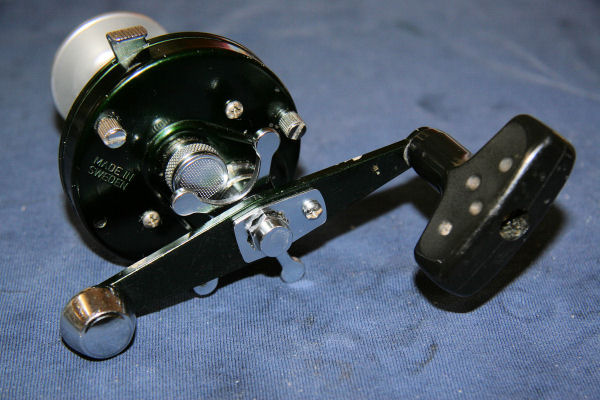
Fig 32: Drag adjuster and handle assembly completed.
For the left hand side, there should be no need to remove the side plate but if you must, then remove the three retaining screws. Fig 33.
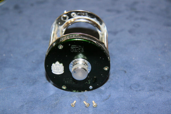
Fig 33: Left hand end plate retaining screws removed.
Gently pull the side plate off watching for anything that might drop out. Inside, there is the magnet slider spring which is a long metal strip that should be attached to the side of the cage, the magnet holder and the magnet holder return spring. The magnet slide adjuster is connected to the magnet slide ratchet by a small screw so will not fall out..Fig 34.
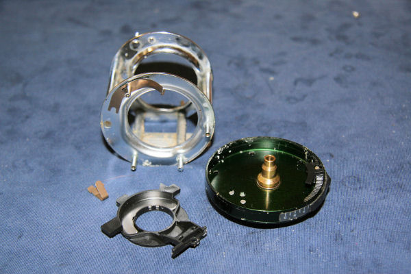
Fig 34. Magnet holder, magnet holder return spring and magnet slider spring. Brass bullet in side plate.
The brass bullet spindle bush should be in the side plate but is easily removed for cleaning. Once cleaned, lightly oil and put back in its recess. Fig 35.
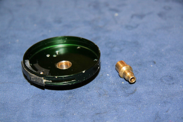
Fig 35: Brass bullet spindle bush.
Once cleaned, put the magnet holder back in place. Fig 36.
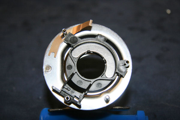
Fig 36: Magnet holder in place.
Put the magnet holder return spring back into its recess as shown. Fig 37.
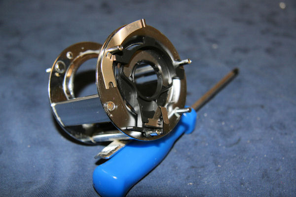
Fig 37: Magnet holder return spring in correct position.
Slide the magnet adjuster slide to halfway and then carefully replace the side plate ensuring that all parts seat correctly. Once the side plate is back on, check that everything works smoothly. You should see the magnet holder moving in and out as the adjuster slide is moved. When you sure it’s all working as it should, secure the side plate with the three screws.
And that’s it, all done. To make sure all is working ok with no problems, check that the spool disengages cleanly and re-engages when the spool is turned by the handle. Check that the drag system works smoothly with no snatching. Make sure that the spool spins smoothly with no excessive noise. In general, does the reel run like new? If any problems encountered, strip it down again and find the source of the problem, don’t leave it until you’re on the beach with the fish of a lifetime on the other end – because you can bet a pound to a pinch of crap that that’s when the reel will fail.
For all reel schematics and part numbers, take a look here
[stextbox id=”grey” caption=”Parts List” color=”000066″ bcolor=”000000″ bgcolor=”e3e1dd”]
Brake blocks: ABU Part no. 22565
Brake block carrier: ABU Part no. 22567
Brake plate: ABU Part no. 23525
Brass bullet: ABU Part no. 23500
Cage: ABU Part no. 811529
Circlip: ABU Part no. 4490
Clutch release arm: ABU Part no. 22077
Clutch release push button: ABU Part no. 20671
Connector arm: ABU Part no. 20685
Drag sprung washers: ABU Part no. 5131
Drag washers – fibre: ABU Part no. 13169 and 20907
Drag washers – stainless steel : ABU Part nos. 20906, 20905 and 20960
Drive shaft: ABU Part no. 22079
Drive shaft shim: ABU Part no. 5189
Handle: ABU Part no. 23080
Handle nut: ABU Part no. 5327
Handle nut retaining tab: ABU Part no. 20944
Handle nut retaining tab screw: ABU Part no. 301
Handle spring washer: ABU Part no. 5115
IAR bush (Instant Anti Reverse): ABU Part no. 22001
Left hand side plate: ABU Part no. 23497
Magnet holder: ABU Part no. 23501
Magnet holder return spring: ABU Part no. 23506
Magnet slide adjuster: ABU Part no. 23504
Magnet slide adjuster screw: ABU Part no. 295
Magnet slider ratchet: ABU Part no. 23523
Magnet slider spring: ABU Part no. 23505
Pinion gear: ABU Part no. 20848
Pinion gear yoke: ABU Part no. 20664
Right hand side plate: ABU Part no. 23507
Sideplate screws: ABU Part no. 304
Spindle retaining clip: ABU Part no. 20090
Spool assembly complete: ABU Part no. 970732 **
Spool bearings: ABU Part no. 13472
Left spool bearing retaining clip: ABU Part no. 10259
Spool release pressure plate: ABU Part no. 20686
Spool spindle: ABU Part no. 802631
Star drag adjuster: ABU Part no. 20925
Tension cap – left hand: ABU Part no. 9597
Tension cap – right hand : ABU Part no. 10239
** Complete spool assembly kit includes x2 13472 bearings, 13104 bearing bush, 22567 brake carrier, 20410 carrier circlip and 10259 bearing retaining clip but no spindle
[/stextbox]


