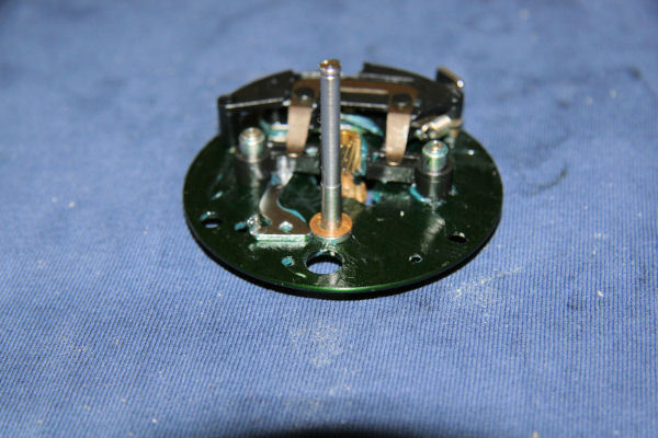
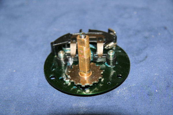
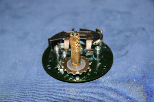
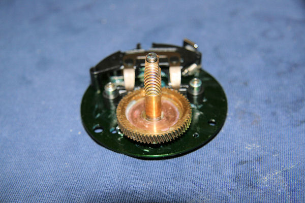
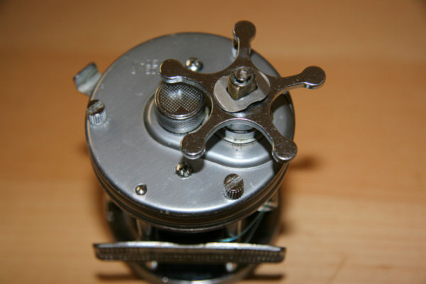
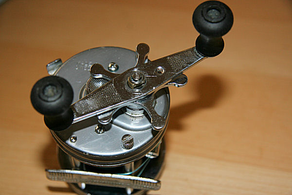
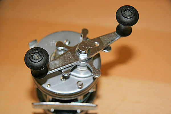
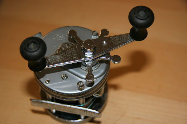
Posts tagged: reel

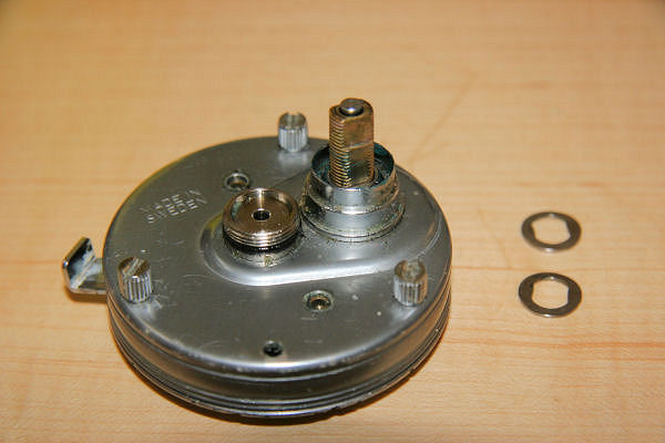
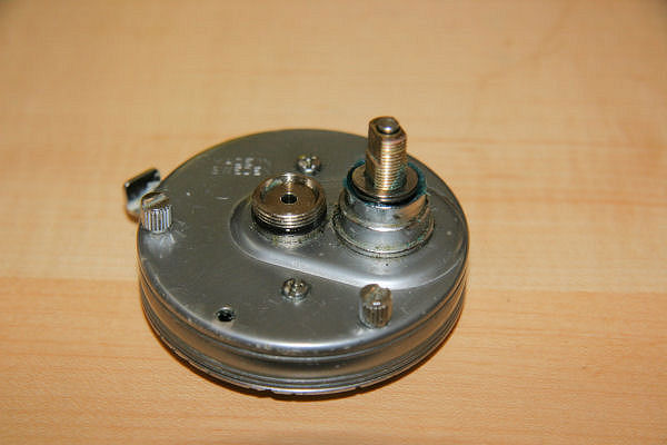
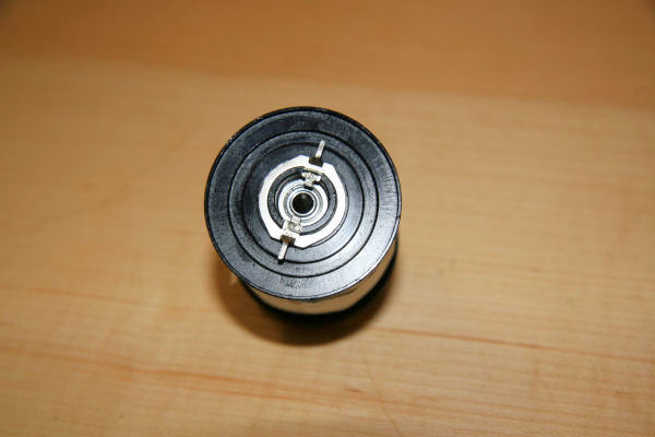
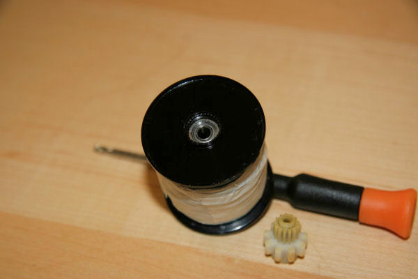
Akios 656CSM strip

By , 20 September, 2011 15:29

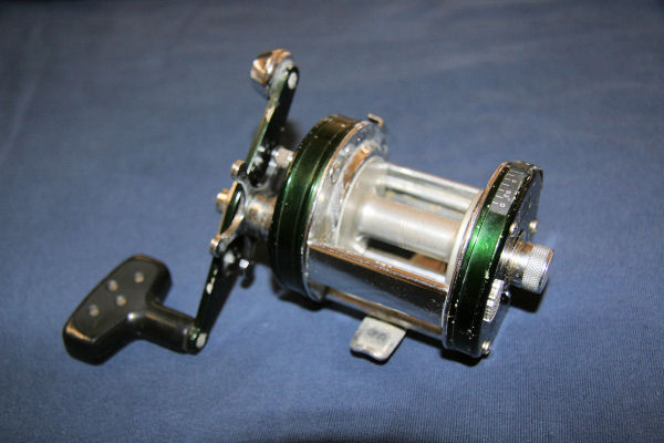
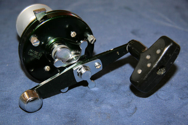
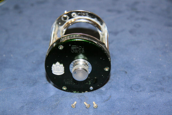
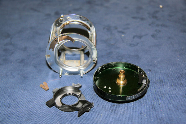
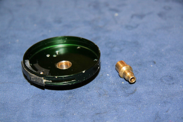
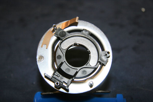
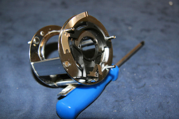
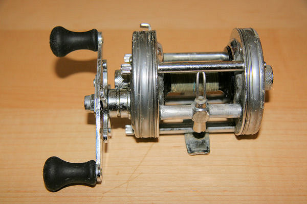
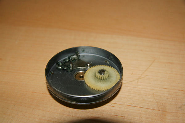
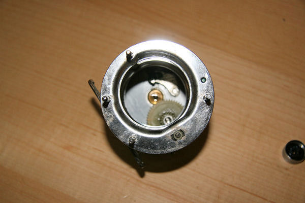
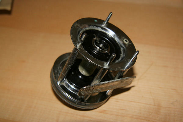
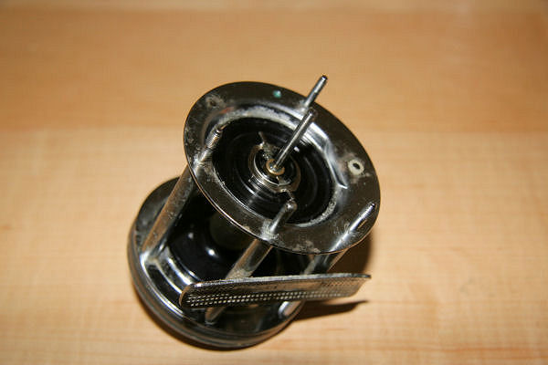
This article is on the Akios S-Line 656 SCM, which which I bought to replace my trusty old ABU 6500 CS Rocket that recently expired after many years of use and abuse. On first looks, the Akios is so similar to the rocket, that it might as well be just a newer version of it. In fact, it is so similar that there probably isn’t any need to do a separate write up on the strip down – but hey, what else can I do to fill the time when I can’t get out fishing?

As I’ve said before, I am not an expert reel technician and this is not meant to be an egg sucking exercise for those who are already familiar with stripping down a reel. This has been done as a guide on to how I strip and clean a reel in the hope that it may help those who are not used to taking these apart.

Hyperlinked part names link to their respective part numbers in the Parts List at the end of the end of the page. Parts and their part numbers shown here pertain to this particular model, so may differ from other reels depending on model and year. I have to say though, that the schematic and parts list is somewhat confusing, in that it often gives multiple part numbers for one part. In this article, I have put the part numbers as given, so if ordering any parts, please be careful and check that you are getting the correct piece.

Print This Post Print This Post Beware, image heavy!
A list of things I use:

  • Clean lint free cloths
  • Suitable solvent (lighter fluid is good)
  • Small flat blade screwdriver
  • Small Phillips screwdriver
  • Spanner to fit handle nut
  • Reel oil
  • Reel grease
  • Small paintbrush
  • Toothbrush

I find that having everything organised first saves time and makes it easier to find the bits that drop off (they will). For this article, I used my trusty white towel – sometimes this is not available as it’s in the wash being cleaned of fish guts and old bait but in this instance was clean(ish).

The first thing to do is give the reel a good rinse and scrub with a toothbrush under running water to remove excess salt and crap and then dry. As you can see, this one didn’t need too much work as it’s virtually brand new. Fig1

Fig 1.

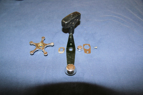
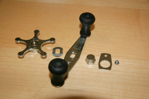
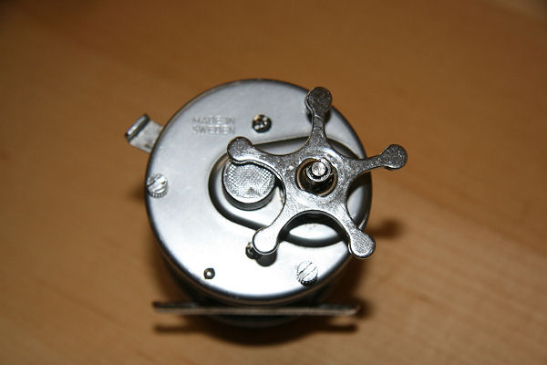
Undo the small screw and remove the retaining tab around the handle nut . Undo the the handle nut and then remove the small E-clip on the top of the shaft to get the handle off. Beware as this is a slippery little sucker and will fly off, either never to be found again or to be found when the nice doctor digs it of your eye. Remove the handle and the small handle spring washer (spacer) under it and then unwind the star drag adjuster until it comes off the shaft. Lay the items out in the order you remove them, to make it easier when re-assembling. Fig 2.

Fig 2


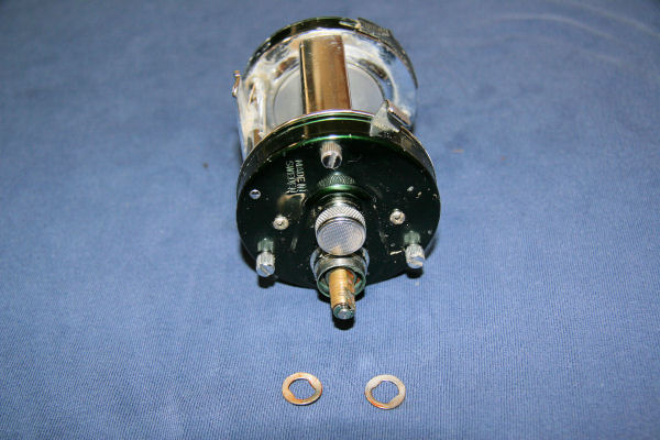
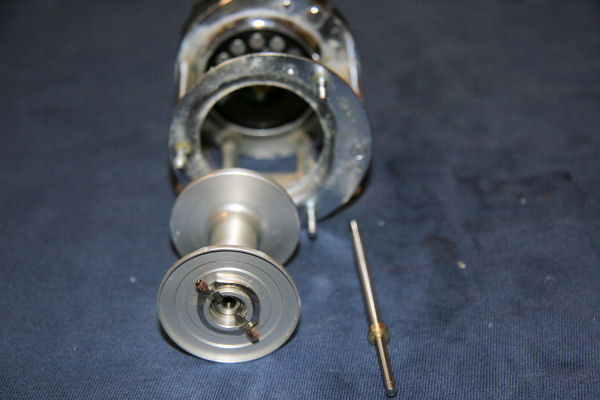
Undo the three knurled captive screws on the right hand side plate and remove it. The spool shaft (spindle) may come out attached to the side plate.  Slide the spool out of the cage and put to one side for the moment. Fig 3.

Fig 3

To prevent losing the small brake blocks and leave you like a dribbling, muttering fool on your hands and knees, slide them off their pins and put in a safe place. Fig 4

Fig 4

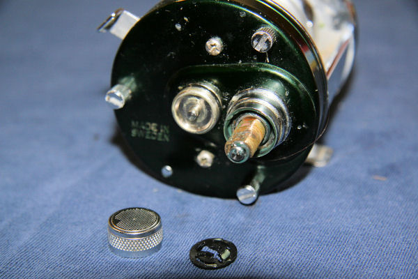
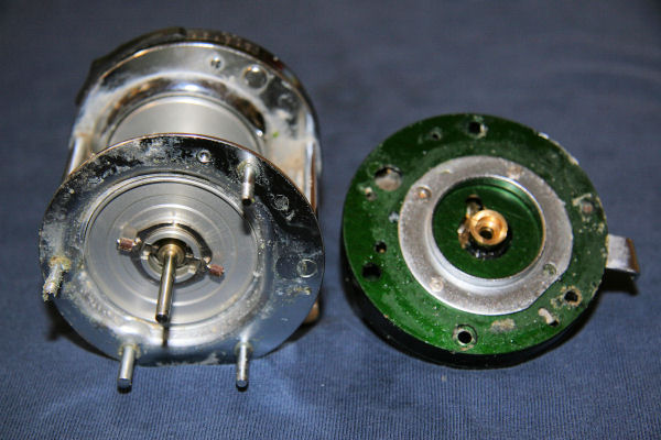
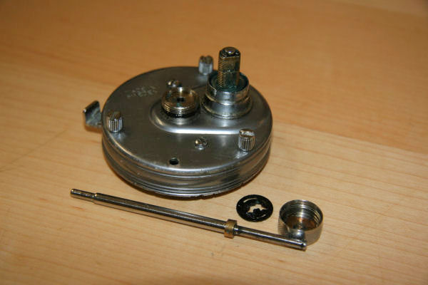
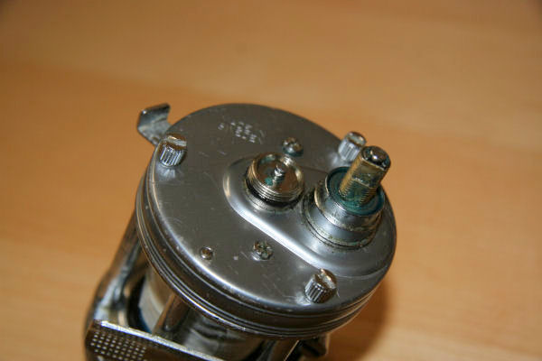
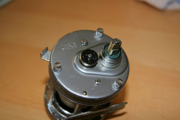
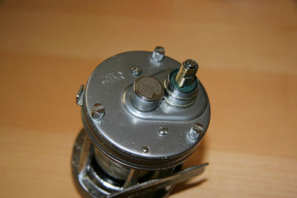
Undo the knurled cast control cap on the end plate and remove the Shaft (spindle) retaining clip and withdraw the spool spindle Fig 5.

Fig 5

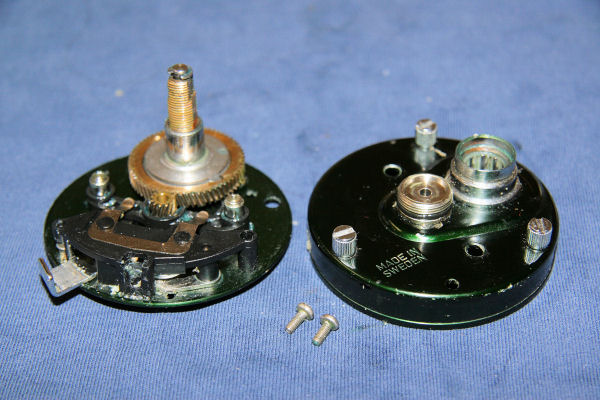
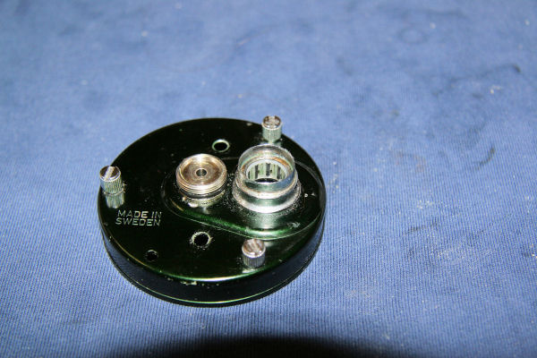
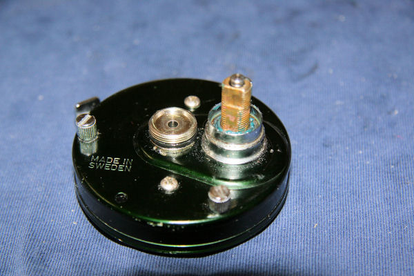
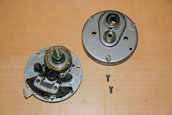
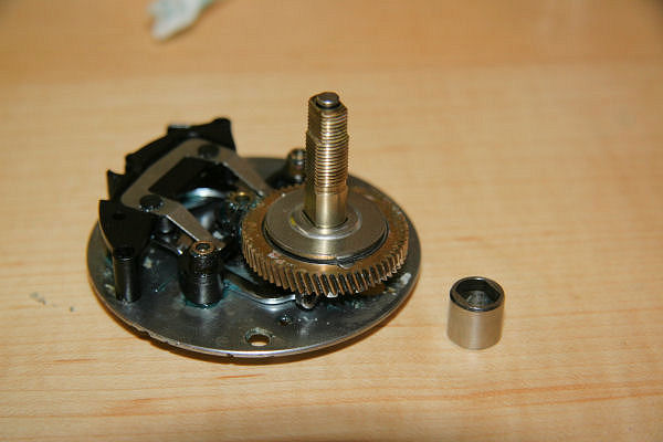
Undo the two smaller side plate screws to release the side plate from the brake plate and the internals. Be careful not to lose the two small plastic washers off the screws, as I reckon they’ll be harder to find than a straight answer from a politician. Pop out the bushing that sits under the knurled cast control cap that was removed in the previous step. You may well find that sitting in the hole left by the drive shaft, will be two spring washers, dig the critters out and put to one side for cleaning. Figs 6, 7, 8 & 9

Fig 6

Fig 7
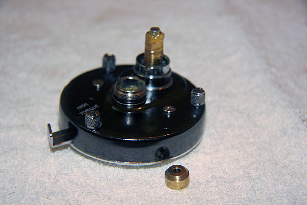
Fig 8

Fig 9

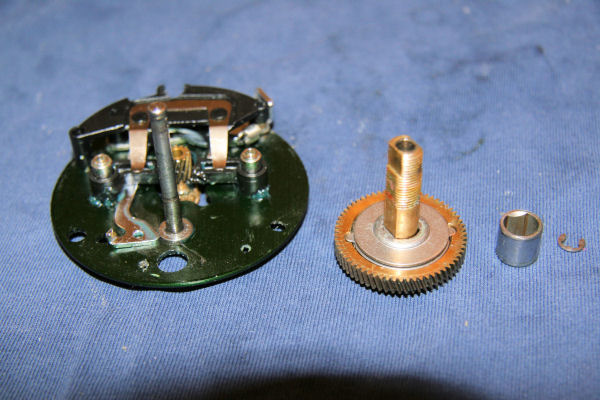
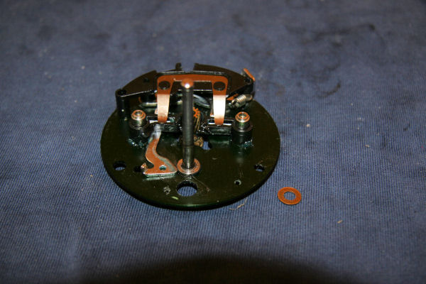
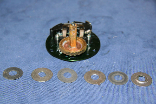
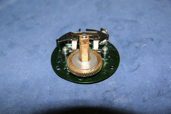
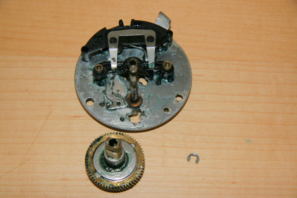
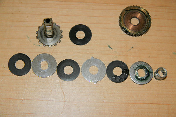
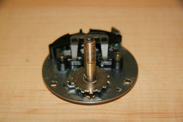
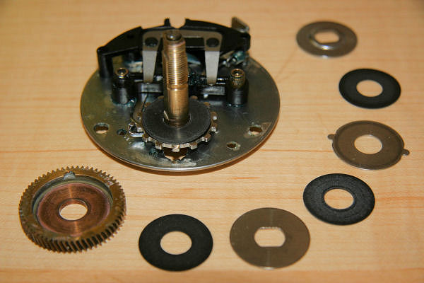
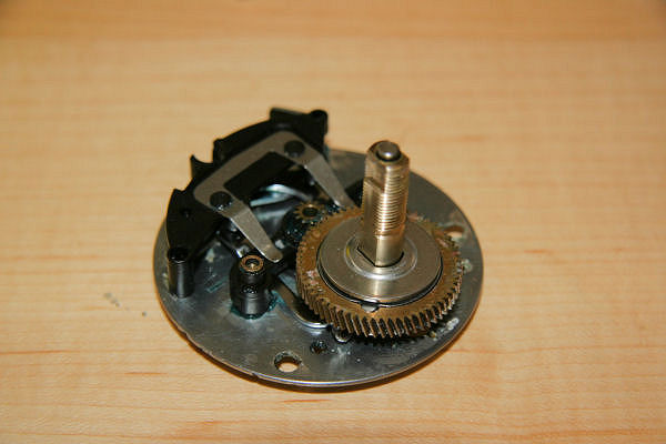
Take the brakeplate assembly and if not already done, remove the small E-clip (heed the warning) at the top of the drive shaft. The drag components, which consist of a mixture of stainless steel washers, fibre washers and other pieces need to be removed. Now you can do this in one of two ways: 1) Pull the shaft and drag assembly off its spindle and then take all the components off , or 2) as I have done here to show the order, take all the components off the shaft first and lay them out in the order they came off. Fig 10. The first method is probably easier but you run the risk of accidentally dropping all the pieces and then not knowing their order; plus they are notoriously difficult, messy and expensive to retrieve from your pet. So here is the order they come off going from right to left – One way bearing (Instant Anti Reverse),> Key washer (domed),> fibre drag washer,> ear washer,> fibre drag washer,> key washer (flat), fibre drag washer,> drive gear,> drive washer

Fig 10

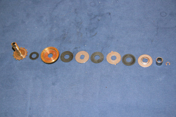
Now remove the drive shaft from the spindle. You will probably find the the release gear will come off attached to the Drive shaft. Now remove the final piece, the tiny spring washer. Fig 11 below, shows all the drive shaft and drag components laid out, in order from right to left with the drive shaft and spring washer above.

Fig 11

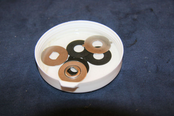
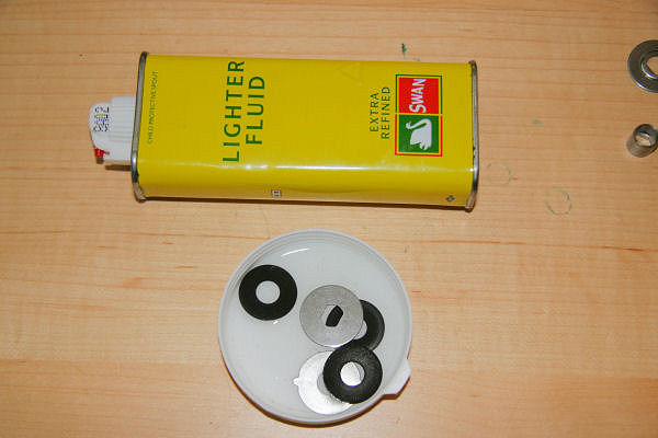
These components may well need a good clean to remove any oil or grease. The easiest way is to get a shallow container, put the components in and cover with lighter fluid (taking all necessary safety precautions of course) and agitate gently them gently for a short while before taking them out and laying on absorbent paper to dry thoroughly. Fig 12.

Fig 12

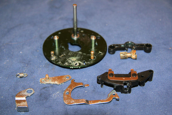
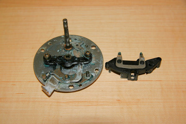
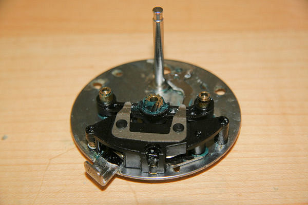
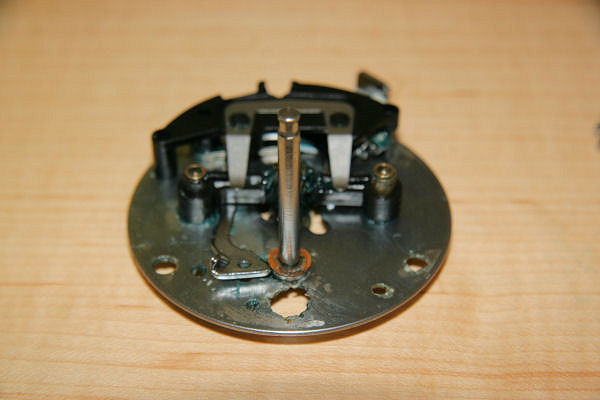
Turning attention to the rest of the innards, remove the support plate Fig 13.
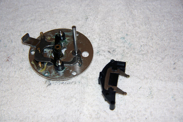
Fig 13

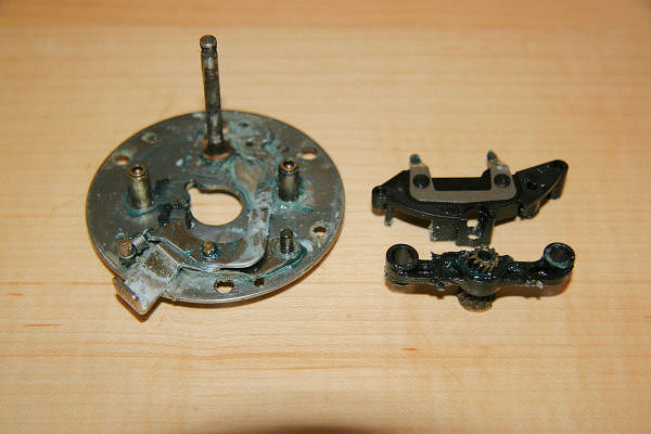
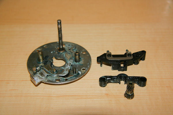
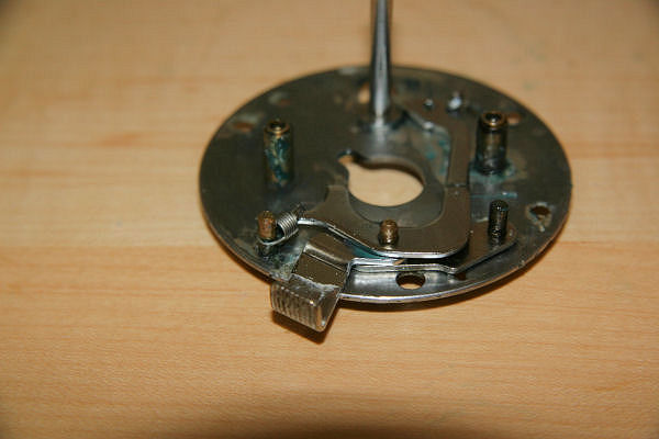
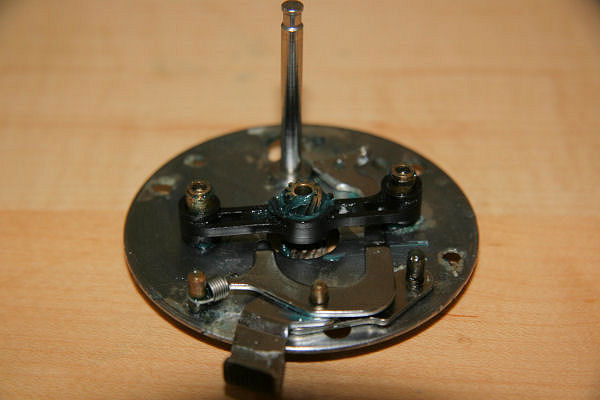
Followed by the pinion gear yoke and pinion gear. Gently push the pinion gear out of the yoke with finger pressure (Remembering which way it goes back – stubby end with the slot faces down) Fig 14.
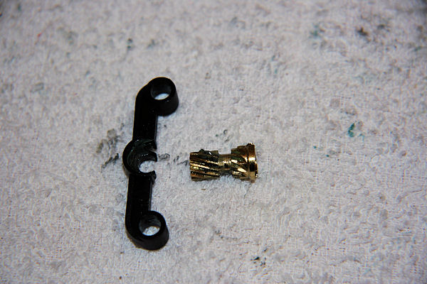
Fig 14

Now lift the clutch plate off its pin. Fig 15.
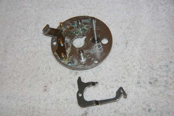
Fig 15

Remove Clutch release trigger (push button). Fig 16.
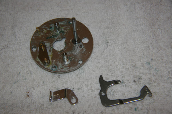
Fig 16

…and the connecting plate Fig 17.
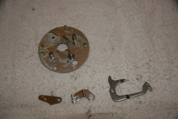
Fig 17

Clean all parts thoroughly to remove old grease, any debris, grit and other nasties. Now time to re-assemble; re-grease all the parts, remembering to grease the pinion yoke and pinion gear. Firstly, slip the connecting plate onto its pin. Fig 18
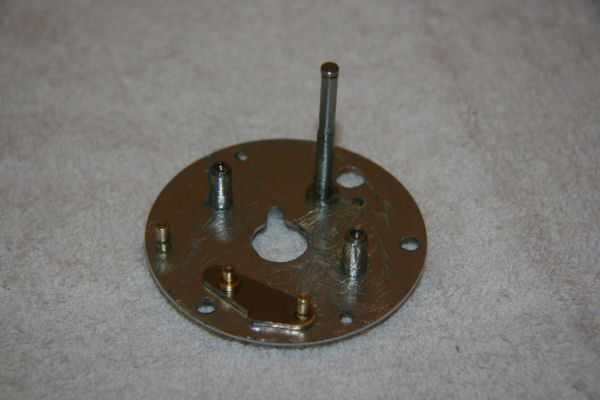
Fig 18

…followed by the trigger (push button). Fig 19
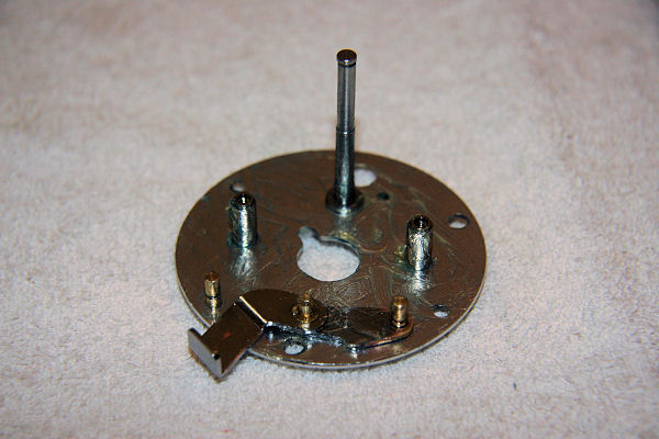
Fig 19

…and clutch plate. Fig 20
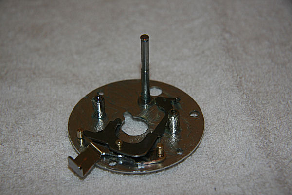
Fig 20

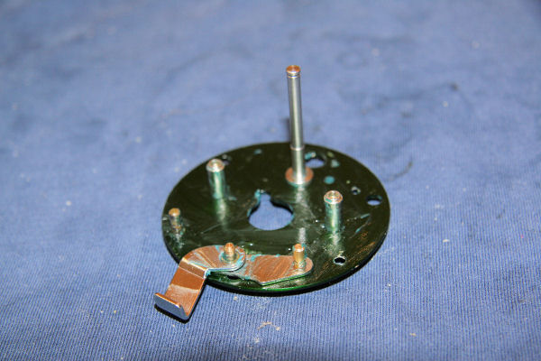
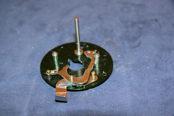
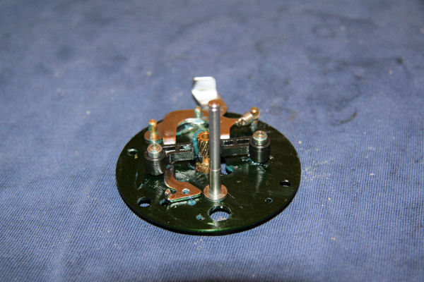
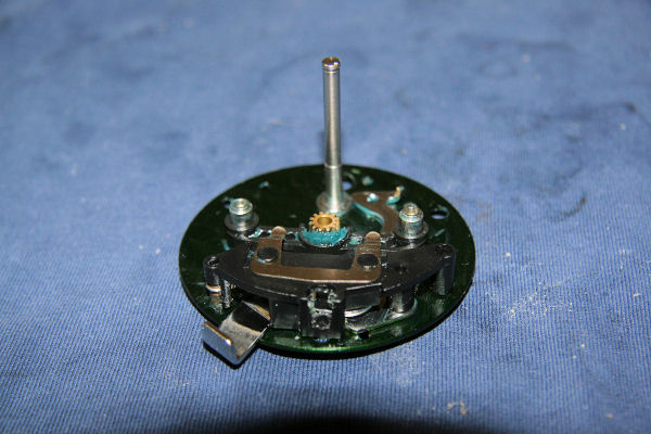
Slip the pinion yoke and gear back on to the two posts. Fig 21
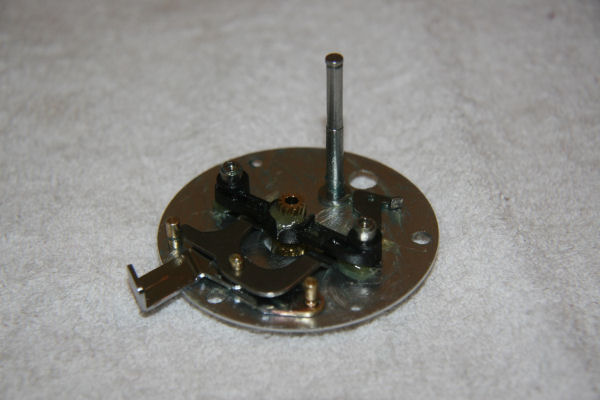
Fig 21

The support plate is next to go on making sure that the spring loaded pin on the left hand side engages with the lobe on the end of the clutch plate. Figs 22 & 23
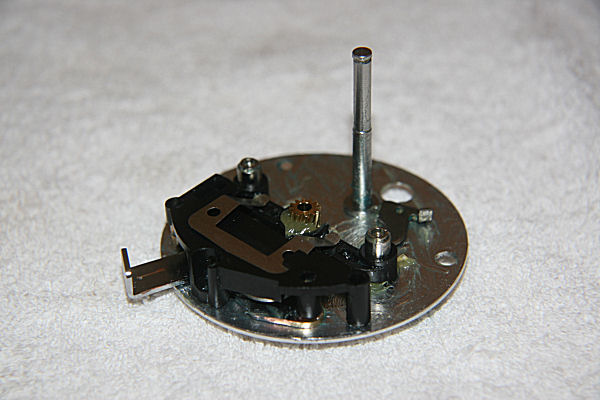
Fig 22
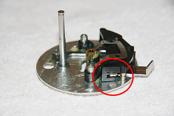
Fig 23

Turning our attention to the drive shaft and drag system, start by replacing the small spring washer onto the spindle, followed by the drive shaft and the attached release gear. Fig 24
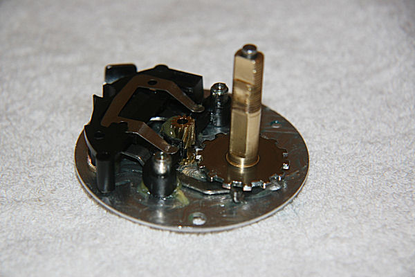
Fig 24

Now rebuild the remained of the system in the following order: Drive washer, drive gear, fibre drag washer, key washer (flat), fibre drag washer, ear washer, fibre drag washer, key washer (domed), one way bearing. Figs: 25, 26, 27, 28, 29, 30, 31, 32 & 33
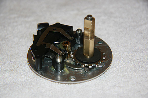
Fig 25
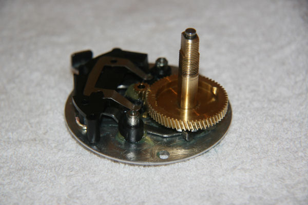
Fig 26
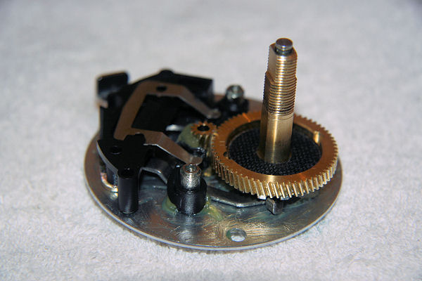
Fig 27
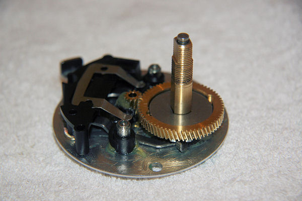
Fig 28
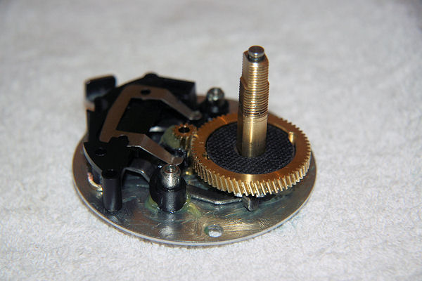
Fig 29
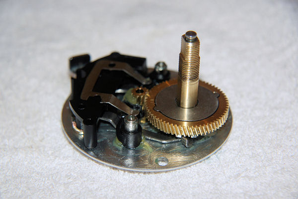
Fig 30
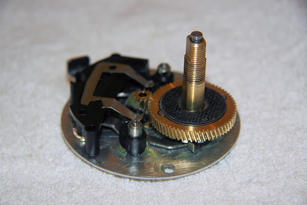
Fig 31
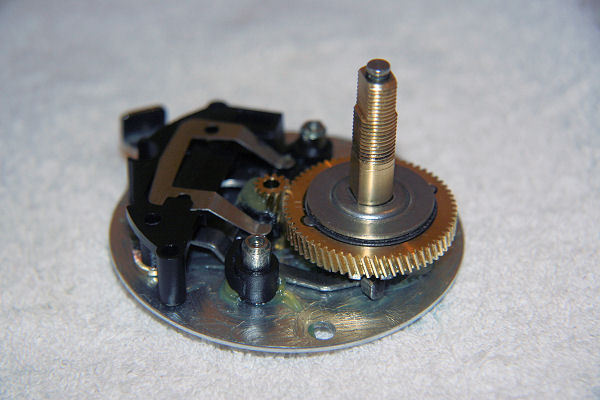
Fig 32
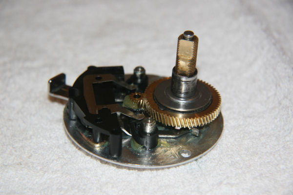
Fig 33

Replace the right hand side plate and secure to the brake plate with the two screws. Fig 34
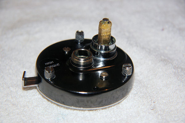
Fig 34

Pop the cast control bush back into its aperture – bevelled end goes in first, leaving the flat end showing. Fig 35
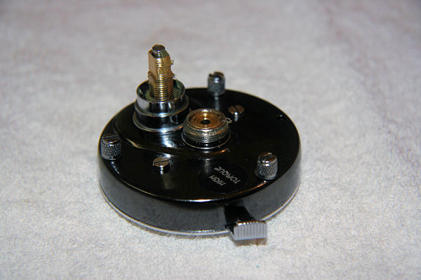
Fig 35

Put all this to one side now, while attention is turned to the other side (left).

Undo the three side plate screws and put in a safe place (these are not captive screws and will escape at the slightest chance). Remove the left side plate. Figs 36 & 37
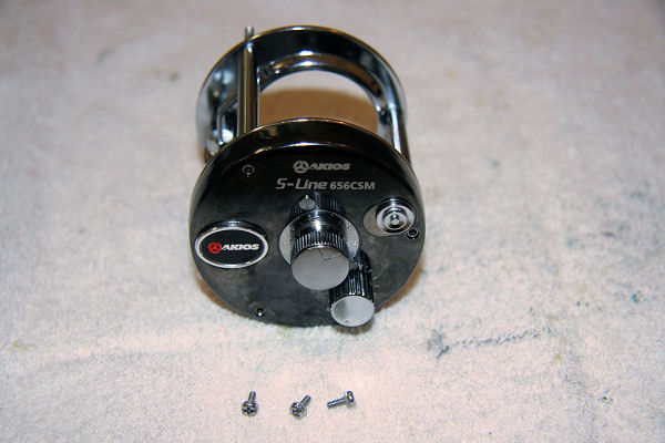
Fig 36
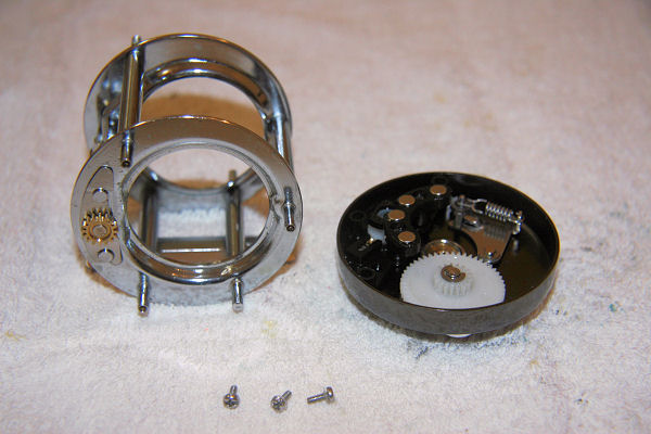
Fig 37

From inside, looking at the magnetic seat (magnet carrier), there is a screw in the centre, which when unscrewed, will release the small knurled magnet adjuster from the carrier and both parts can be removed from the side plate. There is no real need to take things apart any further here unless there are damaged items that need replacing. A general clean out of any debris, grit and old grease will suffice. Before re-assembly, apply a smear of new grease to moving parts and a drop of oil to the spindle of the large white Oscillation cog wheel. Fig 38
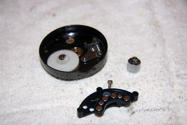
Fig 38

Undo the larger knurled cast control cap and pop out the bushing underneath. A general clean and a drop of oil in the bushing before popping it back in (pointy end goes in the cap) is about all that’s needed here. Fig 39
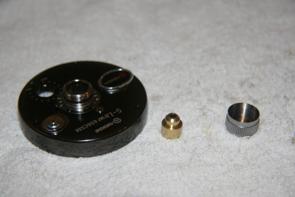
Fig 39

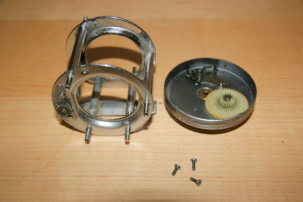
Now for the level wind system. Looking at the end of the cage, release the the thin, curved lock plate by sliding from under the small brass cog. Figs 40 & 41
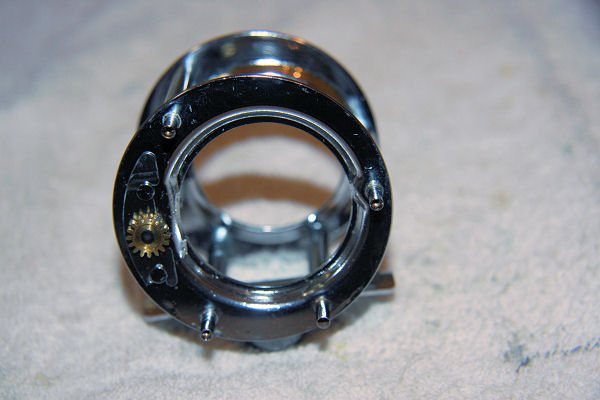
Fig 40
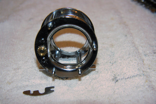
Fig 41

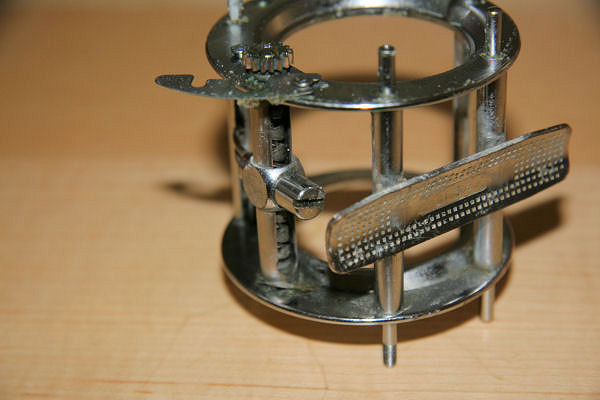
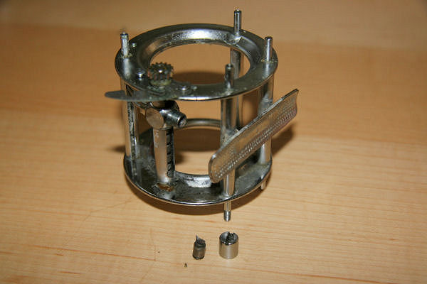
Then turning the reel over, unscrew the level wind nut and pop out the pawl underneath it. Figs 42 & 43
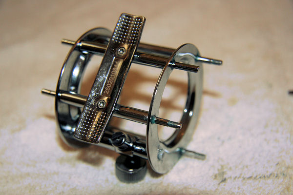
Fig 42
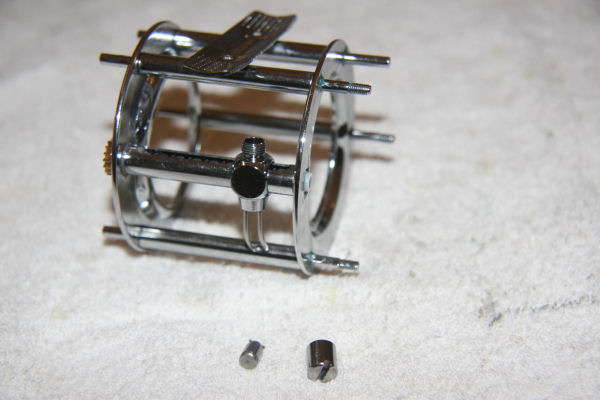
Fig 43

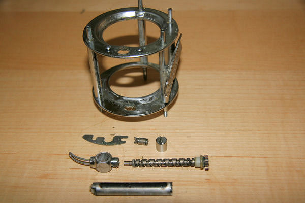
Taking hold of the small brass cog on the end of the cage, carefully withdraw the worm shaft and the line guide, followed by the level wind itself. Fig2s 44 & 45
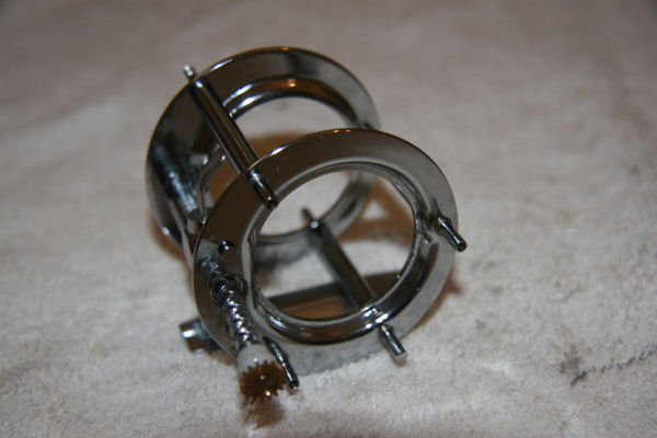
Fig 44
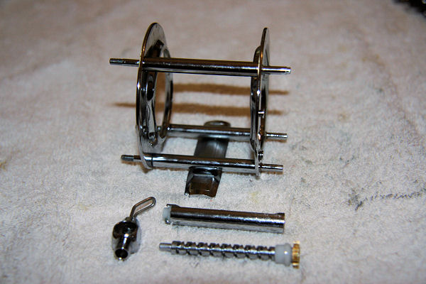
Fig 45

Give all parts a thorough clean to remove the usual, grease, crud and grit. Crap does find its way into the line guide, so I tend to clean it our using one of those ‘Q’ tip type things – which, by the way,  I reckon were designed specifically for the job, long before they were hijacked for cleaning gunk out of ears and other orrifices. Fig 46
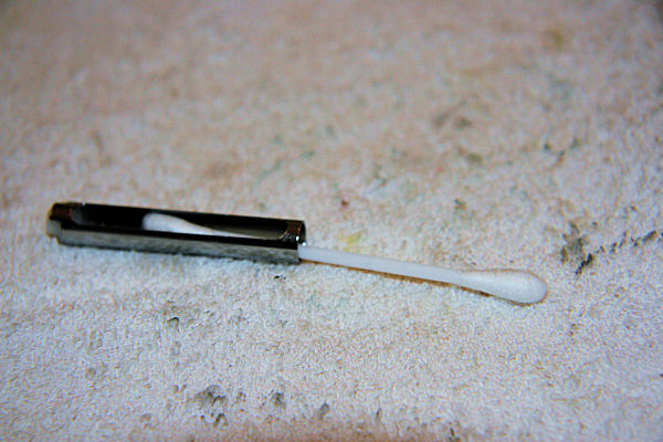
Fig 46

Now that everything is off the cage, it gives a great opportunity to give it a thorough clean, using a fine toothbrush if necessary, to get in all the nooks and crannies. Once everything is clean and shiny, it’s time re-assemble in the reverse order as follows: Fig 47, 48, 49, 50 & 51
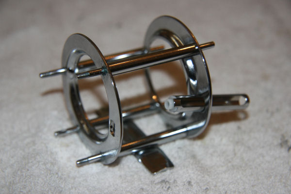
Fig 47
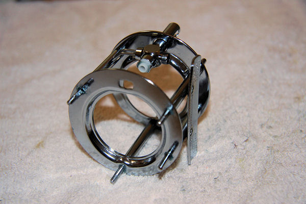
Fig 48
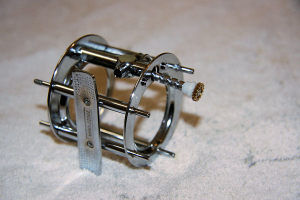
Fig 49
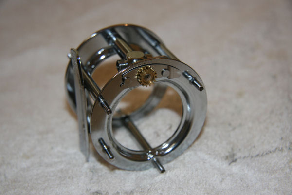
Fig 50
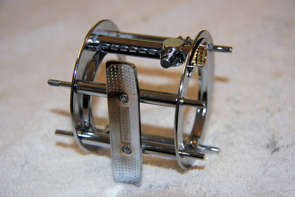
Fig 51
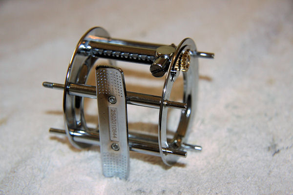
Fig 52

Now all that’s left is to put the side plate back on, check that the screws are secure Fig 53
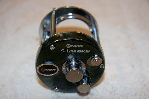
Fig 53

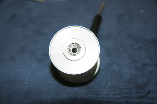
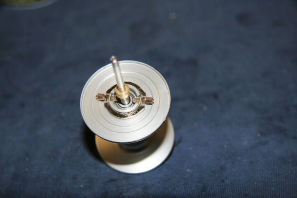
Turning to the spool (if you’ll pardon the pun), normally it only requires a quick clean and drop of oil on the bearings but if the spool seems to be making a weird noises that sound like a coffee grinder, you might want to pop the bearings out for a proper clean, so…. Pull the white plastic line alarm cog wheel off the left side of the spool and gently prise out the bearing from under it. Figs 54 & 55

Fig 54

Fig 55

Then from the other side of the spool, remove the retaining ‘C’ clip ring from under the brake support and then lift off the brake support, before gently prising out the bearing and the washer under it. Fig 56, 57, 58

Fig 56

Fig 57

Fig 58

For a good clean, put the components in a a solvent resistant container and cover in lighter fluid. Agitate all the bits to make sure all old oil and contaminants are removed. Fig 59

Fig 59

Once satisfied that they are clean, remove from the fluid and put on absorbent paper towel or similar and leave to air dry in a dust free space. Once done, re-assemble in reverse order of above. The white cog on the left hand end has two lugs that fit into two spaces on the spool – make sure they engage so that the cog is secure and fits snugly.

Now just to sound one of those lame disclaimers you hear on during or before some TV programmes: (in a stern voice) Please remember to dispose of the lighter fluid in a responsible manner.

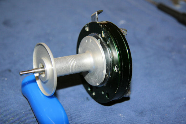
Lightly oil the spool shaft and push through the spool. Insert spool through the right hand side of the cage and locate the end of the shaft into the bushing in the left hand side. Fig 60
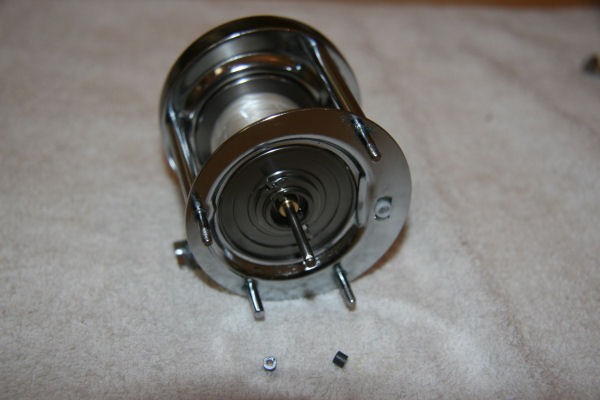
Fig 60

Pop the brakes onto their pins Fig 61
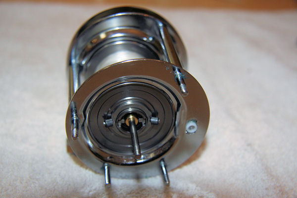
Fig 61

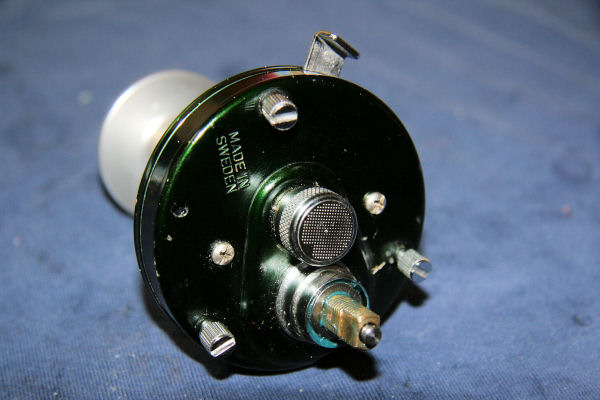
Put the right hand side plate assembly back onto the cage, ensuring that the four posts  correspond to the correct holes. Once back on, do up the knurled captive screws finger tight, before  and replacing the right side cast control cap. Fig 62
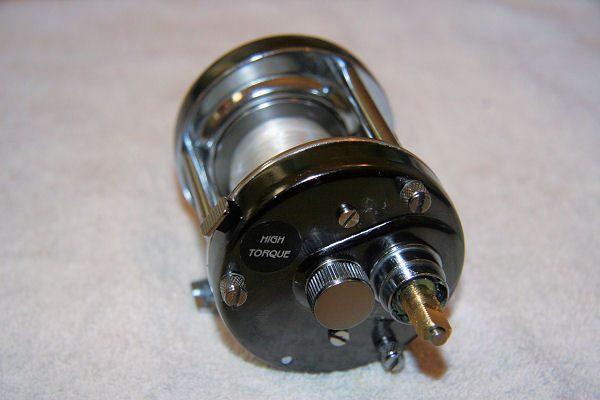
Fig 62

Put the two spring washers back onto the drive shaft and lightly tap them down so that they’re seated well. Fig 63
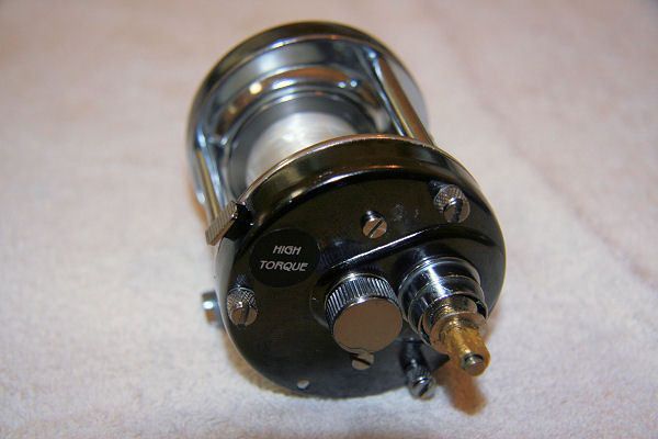
Fig 63

Now put back the last of the components onto the drive shaft in the following order: Star drag adjuster, handle spacer, handle, handle nut,  handle nut retaining plat and finally, the handle nut retainer screw. Figs, 64, 65, 66, 67, 68, 69

Fig 64
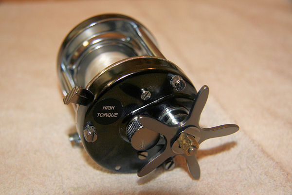
Fig 65
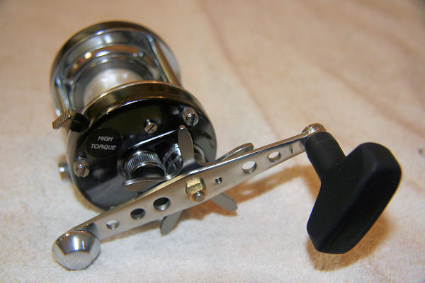
Fig 66
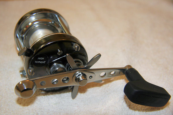
Fig 67

Fig 68


And that’s it, all done. To make sure all is working ok with no problems, check that the spool disengages cleanly and re-engages when the spool is turned by the handle. Check that the drag system works smoothly with no snatchiness. Make sure that the spool spins smoothly with no excessive noise. Ensure that the level wind works correctly. In general, does the reel run like new? If any problems are encountered, strip it down again and find the source of the problem, don’t leave it until you’re on the beach with the fish of a lifetime on the other end – because you can bet a pound to a pinch of crap that that’s when the reel will fail.

For all reel schematics and part numbers, take a look here

 
[stextbox id=”grey” caption=”Parts List” color=”000066″ bcolor=”000000″ bgcolor=”e3e1dd”]

Handle nut retainer screw: Part no. 8907
Handle nut retainer: Part no. HD-6505
Handle nut: Part no. 66119
E-clip: Part no. 8846
Handle assembly: Part no. 66509
Handleknob cap: Part no. 37192
Handle spacer: Part no. 7058
Star drag adjuster: Part no. 66507, 66508, 22631-3
Right side plate assembly: Part nos. 66116, 66101-1, 66102, 6992, L7099, 5326
One way bearing (Instant Anti Reverse): Part no. (not sure – diagram very confusing)
Right cast control cap: Part no. 7604-1
Right cast control bushing: Part no. 66137

‘O’ ring: Part no. 5229-1
Sideplate screws (x2): Part no. 246
Sideplate screw washers (x2): Part no. L7100

Brake plate assembly: Part no. 66130, 66121, 66127, 66128, 66131
Spring plate: Part no. 66126
Support plate: Part nos. 66125, 66132, 66133
Pinion gear yoke: Part no. 66124
Pinion gear: Part no. 66107
Clutch plate: Part no. 66123
Release trigger: Part no. 66135
(connector) Plate: Part no. 66122, 66129

Spring washers (x2): Part no. 66115
Key washer – stainless steel (domed) : Part nos. 66114
Drag washer – fibre (x2): Part no. 66111
Ear washer – stainless steel (eared): Part no. 66112
Key washer – stainless steel (flat): Part no. 66113
Drag washer – fibre: Part no. 66118
Drive gear: Part no. 66109
Drive washer: Part no. 66110
Release gear gear: Part no. 66106
Drive shaft spring washer: Part no. 66108
Drive shaft: Part no. 66105

Shaft retaining clip plate: Part no. 66139
Spool shaft: Part no. 66402, 66407
Spool: Part no. 66401
Spool ball bearings (x2): Part no. 4*10*4(P5)
Bearing washer: Part no. 66404
Centrifugal brake (x2): Part no. 66406
Centrifugal brake support: Part no. 66403
C-Clip: Part no. KAM-9049-1

Sideplate screws (x3): Part no. 199
Left hand side plate: Part no. 66301-2, 66302, 81705-1, 7057, 4491
Left cast control cap: Part no. 7602-1
base washers (x4): Part no. 5145
‘O’ ring: Part no. 5229
Bushing: Part no. 66303

Magnetic seat: Part no. 66314
Magnet switch: Part no. 66313
Washer: Part no. 66316
Lifter: Part no. 66312
Screw: Part no. 246
Magnetic assembly: Part no. 66311, HD-6311
Click: Part no. 66315
Pin: Part no. 66317
Spring (x2): Part no.HD-6309
Screw (x2): Part no. 1-48

Line guide: Part no. 66210
Level wind assembly: Part no. 66213, 22002
Oscillation cog wheel: Part no. 66304
E-clip (x2): Part no. 8846
Level wind Pawl: Part no. 5176
Level wind nut: Part no. 5177
Worm shaft assembly: Part no. 66212, 5170, 66214
Lock plate: Part no. 5178

Line alarm cog wheel: Part no.66405
Click switch: Part no. 8744-1
Click switch washer: Part no. 8904
Click pawl: Part no. 8745
Click pawl spring: Part no. 4464
Click retainer: Part no. 4467
Click E-clip: Part no. 3909
Click spring: Part no. 24390
[/stextbox]

New content ABU 6500C3 CT Mag strip

By , 6 August, 2010 14:23

Just finished doing an article on stripping and cleaning my old ABU 6500C3 CT Mag. Hope it helps.with photos.

Click here

ABU 6500C3 CT Mag Strip

By , 5 August, 2010 23:01

Although this article is on the C3 CT  07, it equally applies to other ABU 6500’s (although part numbers will vary). I am not an expert reel technician and this is not meant to be an egg sucking exercise for those who are already familiar with stripping down a reel. This has been done as a guide on to how I strip and clean a reel in the hope that it may help those who are not used to taking these apart. The one being used here is the twin of the one I stupidly left behind after a recent session and was until now used as a ‘donor’ reel for parts.

Hyperlinked part names link to their respective part numbers in the Parts List at the end of the end of the page. Parts and their part numbers shown here pertain to this particular model, so may differ from other reels depending on model and year.

Print This Post Print This Post Beware, image heavy!
A list of things I use:

  • Clean lint free cloths
  • Suitable solvent (lighter fluid is good)
  • Small flat blade screwdriver
  • Small Phillips screwdriver
  • Spanner to fit handle nut
  • Reel oil
  • Reel grease
  • Small paintbrush
  • Toothbrush

I find that having everything organised first saves time and makes it easier to find the bits that drop off (they will). I sometimes use an old white hand towel for laying the various parts on but for these photos, I didn’t have it, so used my favourite fishing sweatshirt.

The first thing to do is give the reel a good rinse and scrub with a toothbrush under running water to remove excess salt and crap and then dry. As you can see, I didn’t (again). Fig1

Fig 1: Before

Remove the small handle nut retaining tab screw and handle retaining tab around the handle nut . Undo the the handle nut and remove the handle. You may have to remove the small circlip on the top of the shaft to get the handle off but on mine, the handle will come off over it. Beware as this is a slippery little sucker and will fly off into a parallel universe. Next, remove the small handle spring washer and unwind the star drag adjuster until it comes off the shaft. Lay the items out in the order you remove them, to make it easier when re-assembling. Fig2.

Fig 2: Handle and drag adjuster components.

Remove the two drag sprung washers from the drive shaft. Fig 3.

Fig 3: Sprung washers from drive shaft.

Undo the knurled tension cap on the end plate and remove the spindle retaining clip. Fig 4.

Fig 4: Spindle clip and right tension cap.

Undo the three knurled captive screws on the right hand side plate and remove it. Fig 5.

Fig 5: Right side plate removed revealing spool and spindle with brake blocks.

Remove the spool and spindle from the cage and put to one side. Fig 6. If you drop the brake blocks, finding them takes about the same amount of time and is about as successful as finding a cure for the common cold. Put them somewhere safe.

Fig 6: Spool and spindle removed from cage.

Undo the two smaller side plate screws to release the side plate from the brake plate and the internals. Fig 7.

Fig 7: Side plate removed from brake plate, revealing clutch and drag system.

If not already done, remove the small circlip (heed the warning) at the top of the drive shaft and pull the shaft and drag assembly off the spindle. Fig 8.

Fig 8: Drive shaft, main gear and drag assembly removed from spindle.

Now remove the main gear and drag system components from the gear shaft and lay them out in the order they came off. Look after them, as they are notoriously difficult and messy to retrieve from your pet. The drag components consist of a mixture of stainless steel washers and fibre washers Fig 9.

Fig 9: Drive shaft and drag system dismantled.

Remember to remove the small copper drive shaft shim from the base of the spindle and put it with the other drag washers. Fig 10.

Fig 10: Drive shaft shim removed.

These components may well need a good clean to remove any oil or grease. The easiest way is to get a shallow container, put the components in and cover with lighter fluid (taking all necessary safety precautions of course) and agitate gently them gently for a short while before taking them out and laying on absorbent paper to dry thoroughly. Fig 11.

Fig 11: Cleaning components in lighter fluid.

Dismantle the clutch components and lay them out as they come off. Fig 12.

Fig 12: Clutch components

After a through clean and de-cack, dry and lightly grease before re-assembling in the following order: Place the connector arm back onto its post. Fig 13.

Fig 13: Connector arm on its post.

… Followed by the Clutch release push button. Fig 14.

Fig 14: Clutch release push button.

..and the clutch release arm, not forgetting the small spring Fig 15.

Fig 15: Clutch release arm and spring.

After cleaning and re-greasing, click the pinion gear back into the pinion gear yoke making sure it’s the right way in (wider section with the slot goes to the bottom) and push the yoke onto its posts. Fig 16.

Fig 16: Pinion gear and yoke re-installed on posts.

Push the spool release pressure plate into position on its locating pins. Fig 17.  This can be fiddly.

Fig 17: Spool release pressure plate in situ.

Now to re-assemble the drag system. Firstly, put the drive shaft shim back on the spindle. Fig 18.

Fig 18: Drive shaft shim on spindle.

… Followed by the drive shaft itself. Fig 19.

Fig 19: Drive shaft replaced on spindle.

Now put on the smaller of the fibre drag washers. Fig 20.Be careful not to get any grease on the washers. If you do, clean again in lighter fluid and dry thoroughly.

Fig 20: Small fibre washer installed.

Next, slide the main gear back onto the drive shaft. Fig 21.

Fig 21: Main gear located on drive shaft.

…Followed by the drag washers, in this order: fibre, steel, fibre, tabbed steel, fibre, domed steel. Fig 22 and 23.

Fig 22: Drag washers in order L to R.

Fig 23: Drag washers in situ

After cleaning the side plate, add some grease to the IAR (Instant Anti Reverse) bearing located in the larger aperture. Fig 24.

Fig 24: IAR bearing can be seen in the larger aperture.

Now lightly grease and the IAR bearing bush and slide over the drive shaft before replacing the side plate and securing with the two small screws. Fig 25. I should have photographed the bush but forgot; it’s the small stainless steel cylinder as seen in Fig 8 earlier.

Fig 25: Sideplate replaced.

Pop the two sprung washers over the drive shaft and push them down onto the recess. Fig 26.

Fig 26: Sprung washers.

Now we go to the spool. It shouldn’t be necessary to remove the bearings, just a drop of oil to each should suffice. If they need to be removed, one is located under the circular brake block carrier on the right side. Fig 27.

Fig 27: Right side spool bearing under brake block carrier.

… the other is under a thin wire retaining clip on the left side of the spool. Fig 28.

Fig 28: Left spool bearing under wire clip.

Lightly oil the spool spindle and insert it long section first into the right hand end of the spool until the brass collar fits snugly. Gently pop the brake blocks back onto the carrier pins being careful not to get oil or grease on them. Fig 29.

Fig 29: Spool and spool spindle.

Being careful not to dislodge the brake blocks, insert that end of the spindle into the right side plate. Fig 30.

Fig 30: Spool and spindle re-installed into right side plate.

Clip the spindle retaining clip onto the end of the spindle and then screw back the tension cap. Fig 31.

Fig 31: Tension cap replaced.

Now the drag adjuster and handle assembly can be re-fitted in order: adjuster, sprung washer, handle, handle nut, nut retaining plate, screw. Fig 32.

Fig 32: Drag adjuster and handle assembly completed.

For the left hand side, there should be no need to remove the side plate but if you must, then remove the three retaining screws. Fig 33.

Fig 33: Left hand end plate retaining screws removed.

Gently pull the side plate off watching for anything that might drop out. Inside, there is the magnet slider spring which is a long  metal strip that should be attached to the side of the cage, the magnet holder and the magnet holder return spring. The magnet slide adjuster is connected to the magnet slide ratchet by a small screw so will not fall out..Fig 34.

Fig 34. Magnet holder, magnet holder return spring and magnet slider spring. Brass bullet in side plate.

The brass bullet spindle bush should be in the side plate but is easily removed for cleaning. Once cleaned, lightly oil and put back in its recess. Fig 35.

Fig 35: Brass bullet spindle bush.

Once cleaned, put the magnet holder back in place. Fig 36.

Fig 36: Magnet holder in place.

Put the magnet holder return spring back into its recess as shown. Fig 37.

Fig 37: Magnet holder return spring in correct position.

Slide the magnet adjuster slide to halfway and then carefully replace the side plate ensuring that all parts seat correctly. Once the side plate is back on, check that everything works smoothly. You should see the magnet holder moving in and out as the adjuster slide is moved. When you sure it’s all working as it should, secure the side plate with the three screws.


And that’s it, all done. To make sure all is working ok with no problems, check that the spool disengages cleanly and re-engages when the spool is turned by the handle. Check that the drag system works smoothly with no snatching. Make sure that the spool spins smoothly with no excessive noise. In general, does the reel run like new? If any problems encountered, strip it down again and find the source of the problem, don’t leave it until you’re on the beach with the fish of a lifetime on the other end – because you can bet a pound to a pinch of crap that that’s when the reel will fail.

For all reel schematics and part numbers, take a look here

Parts List

[stextbox id=”grey” caption=”Parts List” color=”000066″ bcolor=”000000″ bgcolor=”e3e1dd”]
Brake blocks: ABU Part no. 22565
Brake block carrier: ABU Part no. 22567
Brake plate: ABU Part no. 23525
Brass bullet: ABU Part no. 23500
Cage: ABU Part no. 811529
Circlip: ABU Part no. 4490
Clutch release arm: ABU Part no. 22077
Clutch release push button: ABU Part no. 20671
Connector arm: ABU Part no. 20685
Drag sprung washers: ABU Part no. 5131
Drag washers – fibre: ABU Part no. 13169 and 20907
Drag washers – stainless steel : ABU Part nos. 20906, 20905 and 20960
Drive shaft: ABU Part no. 22079
Drive shaft shim: ABU Part no. 5189
Handle: ABU Part no. 23080
Handle nut: ABU Part no. 5327
Handle nut retaining tab: ABU Part no. 20944
Handle nut retaining tab screw: ABU Part no. 301
Handle spring washer: ABU Part no. 5115
IAR bush (Instant Anti Reverse): ABU Part no. 22001
Left hand side plate: ABU Part no. 23497
Magnet holder: ABU Part no. 23501
Magnet holder return spring: ABU Part no. 23506
Magnet slide adjuster: ABU Part no. 23504
Magnet slide adjuster screw: ABU Part no. 295
Magnet slider ratchet: ABU Part no. 23523
Magnet slider spring: ABU Part no. 23505
Pinion gear: ABU Part no. 20848
Pinion gear yoke: ABU Part no. 20664
Right hand side plate: ABU Part no. 23507
Sideplate screws: ABU Part no. 304
Spindle retaining clip: ABU Part no. 20090
Spool assembly complete: ABU Part no. 970732 **
Spool bearings: ABU Part no. 13472
Left spool bearing retaining clip: ABU Part no. 10259
Spool release pressure plate: ABU Part no. 20686
Spool spindle: ABU Part no. 802631
Star drag adjuster: ABU Part no. 20925
Tension cap – left hand: ABU Part no. 9597
Tension cap – right hand : ABU Part no. 10239

** Complete spool assembly kit includes x2 13472 bearings, 13104 bearing bush, 22567 brake carrier, 20410 carrier circlip and 10259 bearing retaining clip but no spindle
[/stextbox]

New Article added

By , 24 July, 2010 15:14

Just finished doing an article on stripping and cleaning my old ABU 6500 CS Rocket. Hope it helps. Will be doing my Penn 525 soon.

6500 CS Rocket Strip

ABU 6500 CS Rocket Strip

Although this article is on the CS Rocket 01-04, it equally applies to other ABU 6500’s (although part numbers will vary). I am not an expert reel technician and this is not meant to be an egg sucking exercise for those who are already familiar with stripping down a reel. This has been done as a guide on to how I strip and clean a reel in the hope that it may help those who are not used to taking these apart. The one being used here is my old and trusted 6500 CS Rocket (01-04 model) that I’ve had for years and has never let me down even after all the abuse it’s had.

Hyperlinked part names link to their respective part numbers in the Parts List at the end of the end of the page. Parts and their part numbers shown here pertain to this particular model, so may differ from other reels depending on model and year.

Print This Post Print This Post Beware, image heavy!
A list of things I use:

  • Clean lint free cloths
  • Suitable solvent (lighter fluid is good)
  • Small flat blade screwdriver
  • Small Phillips screwdriver
  • Spanner to fit handle nut
  • Reel oil
  • Reel grease
  • Small paintbrush
  • Toothbrush

I find that having everything organised first saves time and makes it easier to find the bits that drop off (they will). I sometimes use an old white hand towel for laying the various parts on but for these photos, I didn’t have it, as it was having fish guts removed in the wash.

The first thing to do is give the reel a good rinse and scrub with a toothbrush under running water to remove excess salt and crap and then dry. As you can see, I didn’t. Fig1

Fig. 1

Remove the small screw and retaining tab around the handle nut . Undo the the handle nut and remove the handle. You may have to remove the small circlip on the top of the shaft to get the handle off but on mine, the handle will come off over it. Beware as this is a slippery little sucker and will fly off, either never to be found again or to be found when the nice doctor digs it of your eye. Next, remove the small handle spring washer and unwind the star drag adjuster until it comes off the shaft. Lay the items out in the order you remove them, to make it easier when re-assembling. Fig2.

Fig. 2

Undo the three knurled captive screws on the right hand side plate and remove it. The spool spindle will come out attached to the side plate.  Slide the spool out of the cage and put to one side for the moment. To prevent losing the small brake blocks and leave you like a dribbling, muttering fool on your hands and knees, slide them off their pins and put in a safe place. Undo the knurled tension cap on the end plate and remove the spindle retaining clip and withdraw the spool spindle Fig 3.

Fig. 3

Undo the two smaller side plate screws to release the side plate from the brake plate and the internals. Fig 4.

Fig. 4

If not already done, remove the small circlip (heed the warning) at the top of the drive shaft and pull the shaft and drag assembly off the spindle. Fig 5.

Fig. 5

Now remove the main gear and drag system components from the gear shaft and lay them out in the order they came off. Look after them, as they are notoriously difficult and messy to retrieve from your pet. The drag components consist of a mixture of stainless steel washers and fibre washers Fig 6.

Fig. 6

These components may well need a good clean to remove any oil or grease. The easiest way is to get a shallow container, put the components in and cover with lighter fluid (taking all necessary safety precautions of course) and agitate gently them gently for a short while before taking them out and laying on absorbent paper to dry thoroughly. Fig 7.

Fig. 7

Turning attention to the rest of the innards, remove the spool release pressure plate Fig 8.

Fig. 8

…and the pinion gear yoke Fig 9.

Fig. 9

Remove pinion gear from the front of the yoke with gentle finger pressure (Remembering which way it goes back – stubby end with the slot faces down) Fig 10.

Fig. 10

Now lift the clutch release arm off its pin after disconnecting from the small spring Fig 11.

Fig. 11

Remove Clutch release push button Fig 12.

Fig. 12

…and the connector arm Fig 13.

Fig. 13

Clean all parts thoroughly with solvent, dry and re-grease with reel grease. Also re-pack the pinion yoke with grease before popping the pinion gear back in (the right way up). Figs 14, 15 and 16

Fig. 14

Fig. 15

Fig. 16

Now re-assemble the clutch release system. Pop the connector arm onto the post as shown Fig 17.

Fig. 17

…and the clutch release push button Fig 18.

Fig. 18

… followed by the clutch release arm, remembering to re-attach the small spring Fig 19.

Fig. 19

Push the pinion yoke – with the pinion gear already fitted in – onto the two posts Fig 20.

Fig. 20

Now push the spool release pressure plate down onto the posts as shown Fig 21.

Fig.21

To re-assemble the main gear and drag system. Lightly grease the drive shaft spindle before sliding the small copper drive shaft shim onto it, followed by the drive shaft Figs 22 and 23.

Fig. 22

Fig. 23

Slide the smaller of the fibre washers onto the drive shaft, followed by the main gear (make sure it engages with the pinion gear) and drag washers in the sequence shown – fibre, stainless steel, fibre, stainless steel tabbed, fibre, stainless steel domed – ensuring that they do not get contaminated with grease or oil. Figs 24 and 25

Fig. 24

Fig. 25

Now slide the IAR bearing bush over the shaft Fig 26.

Fig. 26

Before refitting the side plate onto the backing plate, grease the instant anti reverse (IAR) bearing which is housed in the aperture that slides over the shaft. Once done, slide the side plate over the shaft and secure with the two small screws before sliding the drag sprung washers over the drive shaft. Figs 27 and 28

Fig. 27

Fig. 28

Having finished assembling the right (drive) side, put it to one side and go on to the next part.

Unless you are removing the spool bearings for cleaning or replacement, there’s no need to do much here apart from a light clean to remove any debris and to add a drop of oil to each bearing. On the drive side, the bearing is obvious, sitting under the brake block carrier. Fig 29
**As an aside it should be mentioned that when purchasing the spool, it comes as a complete unit comprising of the spool, bearings, shim, ratchet/level wind drive cog, brake block carrier and circlip. You can still get the component parts separately should you need to**

Fig. 29

The opposite bearing sits under the white plastic ratchet cog which is easily (but gently) prised off with a flat blade screwdriver. Fig 30

Fig. 30

Having done the spool, put it one side with the completed right end plate. Go the other side and remove the three retaining screws and take the left side plate off Fig 31

Fig. 31

To remove the level wind, first unclip one end of the small retaining plate that holds the cog at the end of the level wind worm gear Fig 32

Fig. 32

On the level wind bar, undo the screw and remove the pawl cap. The pawl itself may come out with the cap but if not, gently prise it out with a small flat blade screwdriver. Fig 33

Fig. 33

Now completely remove the worm gear, the small retaining plate, the level wind bar and the level wind guide Fig 34.

Fig. 34

Give all parts a thorough clean before lightly oiling and re-assembling using the reverse order of removal and making sure that the pawl engages fully with the worm gear. Figs 35-38

Fig. 35

Fig. 36

Fig. 37

Fig. 38

The end plate itself requires little doing to it apart from good clean, re-grease of the ratchet system, a drop of oil in the tension end cap and drops of oil in the brass bullet that holds that end of the reel spindle and the spindle of the idler gear (white plastic cog) Figs 39 and 40 before being re-attached with the three small screws.

Fig. 39

Fig. 40

The spool and spindle can now be re-assembled. With the reel cage laying on its left side, drop the spool into place with the small plastic cog end going in first and being careful not to lose the fibre brake blocks. Fig 41

Fig. 41

After lightly oiling, slide the spool spindle into the spool with the brass spacer at the right hand end. Fig 42

Fig. 42

Replace the right (drive side) end plate ensuring that the spool spindle locates properly through the brass pinion gear and protrudes through the end plate. Make sure that the end plate fits correctly before securing it with the knurled captive screws. Fig 43

Fig. 43

Replace the black plastic spindle clip and screw back the tension cap Fig 44 and 45

Fig. 44

Fig. 45

Replace the star drag onto the drive shaft, taking care not to cross thread it and wind it down to the bottom of the shaft Fig 46

Fig. 46

Replace the spring tab and the handle Figs 47 and 48

Fig. 47

Fig. 48

Replace the circlip before replacing the handle nut and tightening Fig 49.

Fig. 49

Now replace the retaining tab and secure it with the small screw Fig 50.

Fig. 50


And that’s it, all done. To make sure all is working ok with no problems, check that the spool disengages cleanly and re-engages when the spool is turned by the handle. Check that the drag system works smoothly with no snatchiness. Make sure that the spool spins smoothly with no excessive noise. Ensure that the level wind works correctly. In general, does the reel run like new? If any problems encountered, strip it down again and find the source of the problem, don’t leave it until you’re on the beach with the fish of a lifetime on the other end – because you can bet a pound to a pinch of crap that that’s when the reel will fail.

For all reel schematics and part numbers, take a look here

Parts List

[stextbox id=”grey” caption=”Parts List” color=”000066″ bcolor=”000000″ bgcolor=”e3e1dd”]
Brake blocks: ABU Part no. 22565
Brake block carrier: ABU Part no. 22567
Brake plate: ABU Part no. 22820
Brass bullet: ABU Part no. 20639
Circlip: ABU Part no. 4490
Clutch release arm: ABU Part no. 22807
Clutch release push button: ABU Part no. 20671
Connector arm: ABU Part no. 20685
Drag sprung washers: ABU Part no. 5131
Drag washers – fibre: ABU Part no. 13169 and 20907
Drag washers – stainless steel : ABU Part nos. 20906, 20905 and 20960
Drive shaft: ABU Part no. 22079
Drive shaft shim: ABU Part no. 5189
Handle: ABU Part no. 20932
Handle nut: ABU Part no. 5327
Handle spring washer: ABU Part no. 5115
IAR bush (Instant Anti Reverse): ABU Part no. 22001
Left hand side plate: ABU Part no. 20840
Level wind bar: ABU Part no. 2496
Level wind guide: ABU Part no. 5174
Main gear: ABU Part no. 21200
Pawl: ABU Part no. 5176
Pawl cap: ABU Part no. 5177
Pinion gear: ABU Part no. 20848
Pinion gear yoke: ABU Part no. 20664
Idler gear: ABU Part no. 5152
Ratchet cog: ABU Part no. 19373
Ratchet system: ABU Part nos. 8744, 8904, 4467, 8745, 4464, 4465 and 3909
Retaining plate: ABU Part no. 5178
Retaining tab: ABU Part no. 20944
Right hand side plate: ABU Part no. 21291
Screw: ABU Part no. 301
Sideplate screws: ABU Part no. 304
Spindle retaining clip: ABU Part no. 20090
Spool: ABU Part no. 970450
Spool assembly: ABU Part no. 970450
Spool bearings: ABU Part no. 13472
Spool release pressure plate: ABU Part no. 22808
Spool spindle: ABU Part no. 802631
Star drag adjuster: ABU Part no. 20925
Tension cap – left hand: ABU Part no. 9597
Tension cap – right hand : ABU Part no. 10239
Worm gear: ABU Part no. 5205
[/stextbox]
Theme adapted from: Panorama theme by Themocracy